element14 Community
element14 Community
    Register Log In
  • Site
  • Search
  • Log In Register
  • Community Hub
    Community Hub
    • What's New on element14
    • Feedback and Support
    • Benefits of Membership
    • Personal Blogs
    • Members Area
    • Achievement Levels
  • Learn
    Learn
    • Ask an Expert
    • eBooks
    • element14 presents
    • Learning Center
    • Tech Spotlight
    • STEM Academy
    • Webinars, Training and Events
    • Learning Groups
  • Technologies
    Technologies
    • 3D Printing
    • FPGA
    • Industrial Automation
    • Internet of Things
    • Power & Energy
    • Sensors
    • Technology Groups
  • Challenges & Projects
    Challenges & Projects
    • Design Challenges
    • element14 presents Projects
    • Project14
    • Arduino Projects
    • Raspberry Pi Projects
    • Project Groups
  • Products
    Products
    • Arduino
    • Avnet Boards Community
    • Dev Tools
    • Manufacturers
    • Multicomp Pro
    • Product Groups
    • Raspberry Pi
    • RoadTests & Reviews
  • About Us
  • Store
    Store
    • Visit Your Store
    • Choose another store...
      • Europe
      •  Austria (German)
      •  Belgium (Dutch, French)
      •  Bulgaria (Bulgarian)
      •  Czech Republic (Czech)
      •  Denmark (Danish)
      •  Estonia (Estonian)
      •  Finland (Finnish)
      •  France (French)
      •  Germany (German)
      •  Hungary (Hungarian)
      •  Ireland
      •  Israel
      •  Italy (Italian)
      •  Latvia (Latvian)
      •  
      •  Lithuania (Lithuanian)
      •  Netherlands (Dutch)
      •  Norway (Norwegian)
      •  Poland (Polish)
      •  Portugal (Portuguese)
      •  Romania (Romanian)
      •  Russia (Russian)
      •  Slovakia (Slovak)
      •  Slovenia (Slovenian)
      •  Spain (Spanish)
      •  Sweden (Swedish)
      •  Switzerland(German, French)
      •  Turkey (Turkish)
      •  United Kingdom
      • Asia Pacific
      •  Australia
      •  China
      •  Hong Kong
      •  India
      •  Korea (Korean)
      •  Malaysia
      •  New Zealand
      •  Philippines
      •  Singapore
      •  Taiwan
      •  Thailand (Thai)
      • Americas
      •  Brazil (Portuguese)
      •  Canada
      •  Mexico (Spanish)
      •  United States
      Can't find the country/region you're looking for? Visit our export site or find a local distributor.
  • Translate
  • Profile
  • Settings
Personal Blogs
  • Community Hub
  • More
Personal Blogs
John Wiltrout's Blog Comparing Power Supplies
  • Blog
  • Documents
  • Mentions
  • Sub-Groups
  • Tags
  • More
  • Cancel
  • New
  • Share
  • More
  • Cancel
Group Actions
  • Group RSS
  • More
  • Cancel
Engagement
  • Author Author: jw0752
  • Date Created: 12 Feb 2017 8:11 PM Date Created
  • Views 3139 views
  • Likes 7 likes
  • Comments 19 comments
  • linear_power_supply
  • switch mode power supply
  • energy_power
Related
Recommended

Comparing Power Supplies

jw0752
jw0752
12 Feb 2017

I recently built a couple of Bench Power Supplies using salvaged parts and inexpensive kits and modules from the Chinese electronics suppliers. I Blogged about these builds here on element-14.


https://www.element14.com/community/people/jw0752/blog/2017/01/24/using-the-coarse-fine-control-circuit-in-my-new-dual-bench-supply


and


https://www.element14.com/community/people/jw0752/blog/2017/02/11/oh-no-not-another-power-supply


It was suggested by michaelkellett that I should do a comparison test to see how well the power supplies perform against each other. I have also added in a comparison to a relatively inexpensive commercial bench supply that is my primary supply.


Here are the three supplies that we will be comparing in this experiment. I will refer to them throughout this blog as the Commercial Supply ( Mastech HY 3005F-3), Linear Supply, and Switching Supply.


image


The Commercial Supply is a 0 to 30V 5 Amp power supply.


image


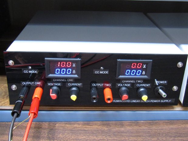
This is the Linear Supply as described in the Blog "Oh No! Not Another #@&* Power Supply" and has a range of 0 to 27 volts with a max 3 Amp current.


image


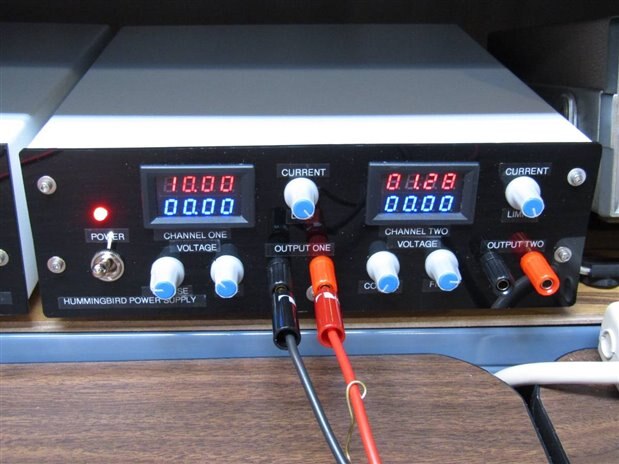
Here is the Switching Supply as described in the Blog "Using the Coarse + Fine Control Circuit in My New Bench Supply"  Which has a voltage output range of 1.2 Volts to 26 Volts with a 5 Amp max current.


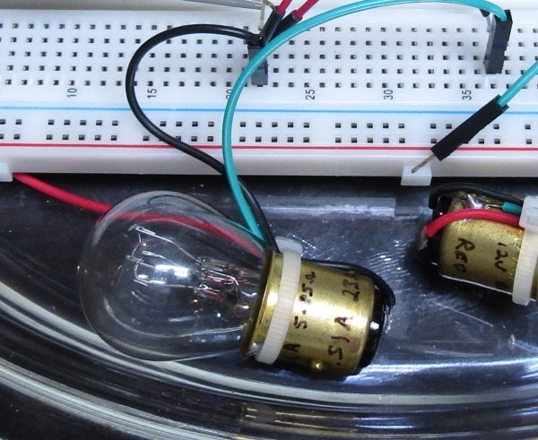
The experiment will look at the ripple of each supply with no load and with full load. Each supply will also be tested and compared to see how it reacts to a load as well as how it reacts to the removal of a load. The test parameters will be 10 volts from channel one of each supply. The load will be an automotive brake light which has a beginning resistance of approximately 0.8 Ohm and an operating resistance of approximately 5.7 Ohms. The low beginning resistance of the bulb will serve to highlight the ability of the power supply to respond to a high current load.


image


The test instrument is a Rigol DS 1102E DSO.


Here is a layout of the test rig wiring.


image


image


I have set up the rig so that both power supplies are switched to their loads simultaneously. One of the weak spots of this experiment is my assumption that the two load bulbs that I will be using are identical. This may not be true in the strictest sense but they will be close enough for the tolerance of this experiment.


Our first test will be to look at supply ripple without and with the load bulbs in the circuit. As a convention when displaying comparisons I will display the Commercial Supply first followed by the Linear Supply and then the Switching Supply. First however let's look at the base line noise on the scope. This is 32 mV PP with the scope probe shorted to its ground wire.


image


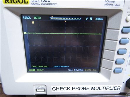
The No Load Trace of the three power supplies is as follows:


    imageimage

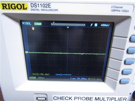
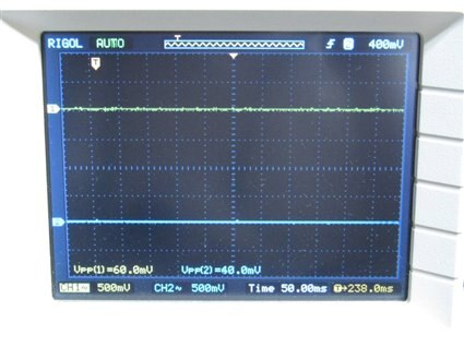
The Commercial Supply has 56 mV PP, the Linear Supply has 60 mV PP and the Switching Supply has 40 mV.


1.75 Amp load on each supply gave the following results:


    imageimage

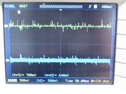
The Commercial Supply has 80 mV PP, the Linear Supply has 700 mV, and the Switching Supply has 640 mV. The characteristic of the switching supply scan is however showing a much more regular pattern which is likely a vestige of the switching frequency.


Next I tested the supply for how they would react to being switched onto the test load.


    imageimage

The Commercial reacts with a 6 volt instantaneous drop that over corrects slightly and stabalizes after 350 ms, The Linear Supply also dips slightly less than 6 volts and also over corrects with a stabilization reached in about 450 ms, and the switching supply reacts with a 3 volt drop and recovers without an over correction to a stable level in about 100 mS.


The last test that I ran was to look at the situation when the load was removed from the supply.


     imageimage

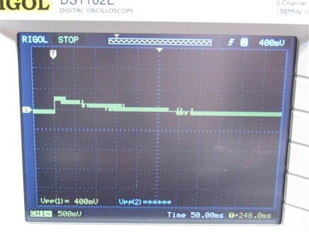
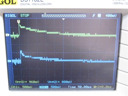
The Commercial supply has the lease reaction with only a 400 mV PP disruption while the Linear had a 960 mV deflection and the Switching had an 800 mV deflection.


My conclusion is that the Commercial at 10 times the cost of the other supplies was the best performer with respect to ripple on the voltage under all test conditions. The surprise for me was that the Switching Supply actually out performed the Linear Supply in my opinion. This was not expected as I had always assumed that the switching supplies would be worse. The obvious switch noise on the Switching Supplies output may be more of a concern than the apparently random noise on the Linear supplies output but I do not know enough to make a proper evaluation of this. I have not gotten to the stage of precision in my experiments so far where I have had any problems . I want to thank Michael for suggesting this experiment as it has given me some potentially valuable insights into the performance of these three supplies.

  • Sign in to reply

Top Comments

  • mcb1
    mcb1 over 8 years ago +2
    Nice test. I suspect that once you add a non linear type load (harmonics, induction), you'll start seeing other differences. The linear supplies we used to make way back suffered from instability, and…
  • jc2048
    jc2048 over 8 years ago +2
    With a 10V supply and a cold load of 0.8 ohms you are asking the supplies to give you 12.5A. The commercial supply current limits and reduces the voltage to 4V (4V/0.8ohms = 5A). It does that nice and…
  • jw0752
    jw0752 over 8 years ago in reply to jc2048 +2
    Thank you Jon for taking the time to give me these excellent insights into what is going on with the results from my tests. Since both Linear supplies have current limiting what you said makes good sense…
Parents
  • jc2048
    jc2048 over 8 years ago

    With a 10V supply and a cold load of 0.8 ohms you are asking the supplies to give you 12.5A. The commercial supply current limits and reduces the voltage to 4V (4V/0.8ohms = 5A). It does that nice and precisely. As the bulb warms, the resistance increases and the PSU can increase the voltage, still on the limiting. That's the initial ramp. When the current is down to 5A, it goes over to voltage control (the handover is a little uncertain) and you have the transient part that you would have measured if you had stuck to the rated current.


    Your linear supply does the same thing, but the current limit isn't precise at all and it's very uncertain at the start, though the handover is better.


    The switcher looks like it limits at about 8.7A, which isn't precise at all if it's meant to be 5A and that might just the limiting it does to protect itself. This time the bulb warms much quicker (obviously). The transient part is quicker than the linears, but not too much so. The switcher has better control of the output - the output smoothing caps are smaller and it can throw them around much quicker.


    It would be worth looking at the noise of your linear supply without the switcher on the other trace (physically disconnect it, don't just turn the trace off; even better turn the switcher itself off). Even with the best scopes, there's a certain amount of contamination between the channels, particularly with spikey, high-frequency noise. If you still see the spikey noise, try turning off other equipment that might be injecting noise through the mains lead. I would not expect 700mV of noise like that from a linear design (where is it going to come from?) - the true noise figure should be a few mV at most. My bench supplies - cheapish ones - quote <1.0mV rms for currents over 3A and <0.5mV rms for currents less than 3A in the spec, though I haven't tried to measure the figures, but I don't remember much in the way of mains filtering (it's a while since I had a look inside one) so they may be prone to feeding noise through.

    • Cancel
    • Vote Up +2 Vote Down
    • Sign in to reply
    • More
    • Cancel
  • jc2048
    jc2048 over 8 years ago in reply to jc2048

    You got me curious as to what I would see with a couple of my own power supplies.


    I had a look at the output of a cheap linear bench supply, GW INSTEK GPS-30300 [usual kind of thing: transistors and opamps, with a pair of 2N3055s for the hard work], and it looks like this. This is x1 with a 20MHz bandwidth limit. To the left, the PSU is off, to the right it's on. No real difference, so any noise from the PSU circuitry is getting lost within the 5mV pk/pk that we see there.


    imageimage


    I'm using a 50ohm coax lead with a terminator at the scope, but it does have croc clips at the PSU end with about 2 inches of unshielded wire. With the scope set to the input GND position, I see about 2mV pk/pk of noise, so the rest is either pickup at the end of the leads, or what is coming through from the mains at the PSU (or maybe the scope end).


    So this one is a bit of a challenge to measure properly using the test equipment that I've got. (Preamp maybe?)


    For comparison, here's a switching supply (Maplin N93CX). This has an output switch. You can see just before the mains goes on it gets slightly quieter - that's my hand moving close to the case. The PSU output control might be electronic - the switch doesn't maintain its state (it always starts up in the off state) and I can't hear a relay clicking. With this supply, the circuitry is definitely contributing to the output noise.


    imageimage


    Not all that rigorous, but it shows the difference between the two. I might try and rig up a transient test later to see if that mirrors what you were seeing.


    Both cases were at an output of 5V with a light load of 10 ohms (0.5A).

    • Cancel
    • Vote Up 0 Vote Down
    • Sign in to reply
    • More
    • Cancel
Comment
  • jc2048
    jc2048 over 8 years ago in reply to jc2048

    You got me curious as to what I would see with a couple of my own power supplies.


    I had a look at the output of a cheap linear bench supply, GW INSTEK GPS-30300 [usual kind of thing: transistors and opamps, with a pair of 2N3055s for the hard work], and it looks like this. This is x1 with a 20MHz bandwidth limit. To the left, the PSU is off, to the right it's on. No real difference, so any noise from the PSU circuitry is getting lost within the 5mV pk/pk that we see there.


    imageimage


    I'm using a 50ohm coax lead with a terminator at the scope, but it does have croc clips at the PSU end with about 2 inches of unshielded wire. With the scope set to the input GND position, I see about 2mV pk/pk of noise, so the rest is either pickup at the end of the leads, or what is coming through from the mains at the PSU (or maybe the scope end).


    So this one is a bit of a challenge to measure properly using the test equipment that I've got. (Preamp maybe?)


    For comparison, here's a switching supply (Maplin N93CX). This has an output switch. You can see just before the mains goes on it gets slightly quieter - that's my hand moving close to the case. The PSU output control might be electronic - the switch doesn't maintain its state (it always starts up in the off state) and I can't hear a relay clicking. With this supply, the circuitry is definitely contributing to the output noise.


    imageimage


    Not all that rigorous, but it shows the difference between the two. I might try and rig up a transient test later to see if that mirrors what you were seeing.


    Both cases were at an output of 5V with a light load of 10 ohms (0.5A).

    • Cancel
    • Vote Up 0 Vote Down
    • Sign in to reply
    • More
    • Cancel
Children
  • jw0752
    jw0752 over 8 years ago in reply to jc2048

    I noticed that when I took my measurements I had the bandwidth switch OFF. When I tested it again with the bandwidth switch on, to cut frequencies above 20 MHz, the amount of noise decreased substantially. The Mastech supply however, looked pretty good with or without the BW switch on.

    John

    • Cancel
    • Vote Up 0 Vote Down
    • Sign in to reply
    • More
    • Cancel
  • jc2048
    jc2048 over 8 years ago in reply to jw0752

    I've added traces showing the results without the bandwidth limit. In the case of the linear supply, it's still the case that the supply doesn't noticeably add to what's there before it's turned on. I'm now wondering about the left switcher trace - how come there's no transient at the point I switched the output on [the switch is recessed and sometimes  I don't operate it properly, so maybe I never actually turned it on]?

    • Cancel
    • Vote Up 0 Vote Down
    • Sign in to reply
    • More
    • Cancel
  • jw0752
    jw0752 over 8 years ago in reply to jc2048

    Hi Jon,

    Did you load the power supply at all when you took your readings? I found that even a 500 mA load was enough to increase the ripple.

    John

    • Cancel
    • Vote Up +1 Vote Down
    • Sign in to reply
    • More
    • Cancel
  • jc2048
    jc2048 over 8 years ago in reply to jw0752

    Yes. The traces above were for 0.5A.


    Here they are for 2A.


    As before, the linear is still just the noise that's fed through from the mains or picked up.


    image


    The switching supply isn't a lot different either - bit less on peak amplitude, maybe.


    image


    This is what the switchers ripple looks like at 2A


    image

    • Cancel
    • Vote Up +1 Vote Down
    • Sign in to reply
    • More
    • Cancel
  • jc2048
    jc2048 over 8 years ago in reply to jw0752

    This is a transient test of the two supplies. This time the output is 10V with the load switching between 0.5A and 2.5A. The load consisted of resistors switched with a power MOSFET.


    [Sorry about this, I seem to be blogging in your blog.]


    Left trace is the switching supply, right is the linear.


    First of all, 0.5A to 2.5A. They both dip by about 3V and get back on course after about 600nS.


    imageimage


    This is a longer view of the above [there's a 10V offset, so the marker is actually at 10V and not 0V]. The switcher is wobbling around for a long time after.


    imageimage


    Finally, 2.5A to 0.5A [again with the 10V offset, so they're both getting up over 20V]. Again fairly similar.


    imageimage

    • Cancel
    • Vote Up +1 Vote Down
    • Sign in to reply
    • More
    • Cancel
element14 Community

element14 is the first online community specifically for engineers. Connect with your peers and get expert answers to your questions.

  • Members
  • Learn
  • Technologies
  • Challenges & Projects
  • Products
  • Store
  • About Us
  • Feedback & Support
  • FAQs
  • Terms of Use
  • Privacy Policy
  • Legal and Copyright Notices
  • Sitemap
  • Cookies

An Avnet Company © 2025 Premier Farnell Limited. All Rights Reserved.

Premier Farnell Ltd, registered in England and Wales (no 00876412), registered office: Farnell House, Forge Lane, Leeds LS12 2NE.

ICP 备案号 10220084.

Follow element14

  • X
  • Facebook
  • linkedin
  • YouTube