element14 Community
element14 Community
    Register Log In
  • Site
  • Search
  • Log In Register
  • Community Hub
    Community Hub
    • What's New on element14
    • Feedback and Support
    • Benefits of Membership
    • Personal Blogs
    • Members Area
    • Achievement Levels
  • Learn
    Learn
    • Ask an Expert
    • eBooks
    • element14 presents
    • Learning Center
    • Tech Spotlight
    • STEM Academy
    • Webinars, Training and Events
    • Learning Groups
  • Technologies
    Technologies
    • 3D Printing
    • FPGA
    • Industrial Automation
    • Internet of Things
    • Power & Energy
    • Sensors
    • Technology Groups
  • Challenges & Projects
    Challenges & Projects
    • Design Challenges
    • element14 presents Projects
    • Project14
    • Arduino Projects
    • Raspberry Pi Projects
    • Project Groups
  • Products
    Products
    • Arduino
    • Avnet Boards Community
    • Dev Tools
    • Manufacturers
    • Multicomp Pro
    • Product Groups
    • Raspberry Pi
    • RoadTests & Reviews
  • Store
    Store
    • Visit Your Store
    • Choose another store...
      • Europe
      •  Austria (German)
      •  Belgium (Dutch, French)
      •  Bulgaria (Bulgarian)
      •  Czech Republic (Czech)
      •  Denmark (Danish)
      •  Estonia (Estonian)
      •  Finland (Finnish)
      •  France (French)
      •  Germany (German)
      •  Hungary (Hungarian)
      •  Ireland
      •  Israel
      •  Italy (Italian)
      •  Latvia (Latvian)
      •  
      •  Lithuania (Lithuanian)
      •  Netherlands (Dutch)
      •  Norway (Norwegian)
      •  Poland (Polish)
      •  Portugal (Portuguese)
      •  Romania (Romanian)
      •  Russia (Russian)
      •  Slovakia (Slovak)
      •  Slovenia (Slovenian)
      •  Spain (Spanish)
      •  Sweden (Swedish)
      •  Switzerland(German, French)
      •  Turkey (Turkish)
      •  United Kingdom
      • Asia Pacific
      •  Australia
      •  China
      •  Hong Kong
      •  India
      •  Korea (Korean)
      •  Malaysia
      •  New Zealand
      •  Philippines
      •  Singapore
      •  Taiwan
      •  Thailand (Thai)
      • Americas
      •  Brazil (Portuguese)
      •  Canada
      •  Mexico (Spanish)
      •  United States
      Can't find the country/region you're looking for? Visit our export site or find a local distributor.
  • Translate
  • Profile
  • Settings
Personal Blogs
  • Community Hub
  • More
Personal Blogs
John Wiltrout's Blog Decentralized Power Distribution Architecture
  • Blog
  • Documents
  • Mentions
  • Sub-Groups
  • Tags
  • More
  • Cancel
  • New
  • Share
  • More
  • Cancel
Group Actions
  • Group RSS
  • More
  • Cancel
Engagement
  • Author Author: jw0752
  • Date Created: 20 Jan 2019 6:29 AM Date Created
  • Views 638 views
  • Likes 12 likes
  • Comments 6 comments
  • mp2363
  • distributed power architecture
Related
Recommended

Decentralized Power Distribution Architecture

jw0752
jw0752
20 Jan 2019

About 6 months ago we had an Essential Post on Power Distribution:


Smart Power Distribution


Tonight as I studied a junk circuit board in my bin I came across a good example of the De-Centralized Architecture.


image

This is a board from an upscale Audio Video Sound System Receiver. The board has multiple micro processors which usually don't have much interest for me but in the lower right corner of the board I saw a parts layout that was repeated 4 times. The IC at the center of each repetition was an MP2363DN which turns out to be a 3A 365 kHz Step Down Converter.


Here is the Data Sheet if you are interested:


https://datasheet.octopart.com/MP2363DN-LF-Monolithic-Power-Systems-datasheet-13696477.pdf


The section of the Data Sheet that first caught my eye was the typical application circuit:


image

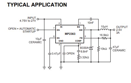
As I traced out and checked the circuits on the board it appeared that the designer had used the Typical Application for the configuration. The data Sheet also had information on using a resistor voltage divider to set the voltage output. I decided that it would be a fun exercise to figure out what resistors were used in each section and apply the formulas in the data sheet to predict the output voltage  of each section. I numbered the sections 1 to 4 left to right. Here are the formulas for setting output voltage:


image


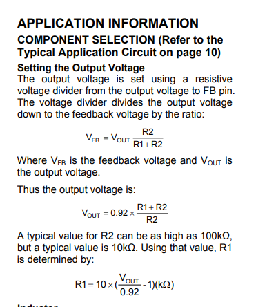
This was extra fun as the designer had used parallel resistors to trim his required value for R-1 in each section. I tried to measure the R1 combination in circuit with my meter but it was obvious that other components were messing with my readings. Since the readings on the resistors were legible I was able to read and calculate them as #1 - 1.525k, #2 - 10k, #3 - 26k, #4 - 46k. Inserting these into the formulas yielded the following output voltages respectively:  1 volt, 1.84 volts, 3.3 volts, and 5.1 volts.


Now I wanted to test my calculations. I had no way to power the board like it was in the receiver but I could easily power the rails that fed these four circuits. I set up a couple of 10 volt power wires with Non-Slip Probe Tips and placed them so that I had 10 volts plus on pin 2 of chip #1 and ground on pin 4 of the same chip. Since this fed the rails for all four circuits no further movement was needed. I had already tied my multimeter negative probe to ground and while holding the power probes with one hand I probed the output of each of the 4 DC to DC converters. The result was 1.2 volts, 1.9 volts, 3.4 volts, and 5.2 volts respectively which matched very well with my calculations.


image


This is the first time I have encountered such an obvious example of the Distributed Power Architecture that was mentioned in the Essential Power Blog. It was fun to experiment with the circuit and who knows somewhere down the line I may even have an application for the MP2363 Step Down Converter Chip.


John

  • Sign in to reply

Top Comments

  • jw0752
    jw0752 over 6 years ago +5
    Red 12+ Black Ground White 1 V Orange 1.7 V Blue 3.3 V Brown 5.3 V Tonight I decided to see if I could excise the 4 Step Down circuits from the larger board and still have an operational power section…
  • DAB
    DAB over 6 years ago +4
    Good job of reverse engineering John. We will make an electronics engineer out of you yet. DAB
  • jw0752
    jw0752 over 6 years ago in reply to DAB +4
    Thanks DAB, Engineer? Too much responsibility. Better as a technician where I can point my finger at the engineer if something goes wrong. John
  • jw0752
    jw0752 over 6 years ago

    One of the things I like to do is to order in a component like the MP2363 and then bread board it and play with it. Since the parts arrived today I mount the MP2363 on an adapter board and built the recommended circuit around it. The chip comes with a central solder pad that is tied to ground which my adapter board did not support but at the current levels (up to 500 mA) that I tested, it did not seem to matter.


    image


    Initially I put a 1K resistor across the output for a load but soon added the Electronic load and settled on a 250 mA load. The unit is advertised to operate at 365 kHz and this one was solid at 347.2 kHz. I set the control resistors up to produce the 2.5 volts in the recommended circuit and then I experimented, replacing the 16.9K resistor to get higher voltages and lower voltages. For my final tests I settled on a 47K resistor which produced an output of 5.3 volts. Tests were made at various input voltages and loads up to 500 mA. The unit was stable as long as the input voltage was 2 volts above the output voltage. I could detect no significant heat in the MP2363 even at 500 mA.  Here is a picture of a wider view of the lay out:


    image


    I initially had some problems getting the circuit to work properly but as is usually the case it was me forgetting to provide the poor thing with a critical component or connection. In this case I forgot to tie the pin 4 to ground. Surprisingly the unit worked even without the ground but the frequency was 42 kHz and the output had no ability to support a load. Go figure!. Once the ground was attached no further problems were encountered


    Here is the instrumentation:


    image


    At the time of this picture the input voltage was 13.3 Volts and the input current was 120 mA. Output voltage was 5.3 Volts and the load on the output was 257 mA. My calculator says that that is 85% efficiency which isn't bad considering the long wires and bread board configuation.


    The MP2363 is a great little Step Down Converter and of course it was a lot of fun to play with.


    John

    • Cancel
    • Vote Up +2 Vote Down
    • Sign in to reply
    • More
    • Cancel
  • DAB
    DAB over 6 years ago in reply to jw0752

    There are many types of engineers.

    There was and probably still is a thriving market for people who can reverse engineer legacy equipment.


    DAB

    • Cancel
    • Vote Up +2 Vote Down
    • Sign in to reply
    • More
    • Cancel
  • jw0752
    jw0752 over 6 years ago

    image

    Red 12+   Black Ground   White 1 V   Orange 1.7 V   Blue 3.3 V   Brown 5.3 V


    Tonight I decided to see if I could excise the 4 Step Down circuits from the larger board and still have an operational power section. I studied the layout and made my best guess as to where I could cut the board and not cut required circuitry. I used the SMD rework station to get a couple of larger ICs out of the way of the saw. When I first powered up the unit after cutting I had only the 5.5 volt section working. Trouble shooting and comparison of the sections showed that the enable pin 7 of the three down MP2363s was low. The data sheet indicates that pin 7 should be allowed to float for auto power up. The 5.5 volt section was already open but the other 3 sections were tied back to one of the chips I had removed to avoid the saw cut. Apparently the 1V, 1.7V, and 3.3V were designed to be powered on at the control of the chip I removed. With this insight I cut the trace to pin 7 on each of the non-functional MP2363s and tried once again to see if the unit was working. Once I had the unit working I also added a load to each channel. I did not try the three amps advertised in the data sheet as my jumper wires would have been stressed by this amount but I did subject each section individually to 2 Amps of load. To me it is simply amazing that these small DC converters can deliver 3 Amps with so little heat and such amazing voltage stability.


    image


    Simple experiments like this one always seem to net a little additional knowledge. Now I know that I can turn the chips on and off with the number 7 enable pin. This information was in plain sight in the data sheets but it always helps my learning process if I have to get physically involved with the process.


    Now I have to keep this circuit in mind so I can incorporate it into a future build somehow.


    John

    • Cancel
    • Vote Up +5 Vote Down
    • Sign in to reply
    • More
    • Cancel
  • jw0752
    jw0752 over 6 years ago in reply to DAB

    Thanks DAB,


    Engineer?  Too much responsibility. Better as a technician where I can point my finger at the engineer if something goes wrong. image


    John

    • Cancel
    • Vote Up +4 Vote Down
    • Sign in to reply
    • More
    • Cancel
  • DAB
    DAB over 6 years ago

    Good job of reverse engineering John.

    We will make an electronics engineer out of you yet.


    DAB

    • Cancel
    • Vote Up +4 Vote Down
    • Sign in to reply
    • More
    • Cancel
>
element14 Community

element14 is the first online community specifically for engineers. Connect with your peers and get expert answers to your questions.

  • Members
  • Learn
  • Technologies
  • Challenges & Projects
  • Products
  • Store
  • About Us
  • Feedback & Support
  • FAQs
  • Terms of Use
  • Privacy Policy
  • Legal and Copyright Notices
  • Sitemap
  • Cookies

An Avnet Company © 2025 Premier Farnell Limited. All Rights Reserved.

Premier Farnell Ltd, registered in England and Wales (no 00876412), registered office: Farnell House, Forge Lane, Leeds LS12 2NE.

ICP 备案号 10220084.

Follow element14

  • X
  • Facebook
  • linkedin
  • YouTube