


Tonight an older Dental Electro-surgery Unit was sent to me for repair. The dentist uses an Electro-Surgery unit like a scalpel to remove growths from inside the mouth and also to cauterize areas of tissue. The hand piece has a chuck and will accommodate different size and shape ends to suit different types of lesions. When I was more active in the dental repair business I would keep a piece of meat in the refrigerator so that I could test the repaired units by cutting out small pieces of meat and cauterizing patterns on the face of the steak.
If you would like more details on how the process works here is a link that explains Electro-Surgery in more detail:
https://en.wikipedia.org/wiki/Electrosurgery
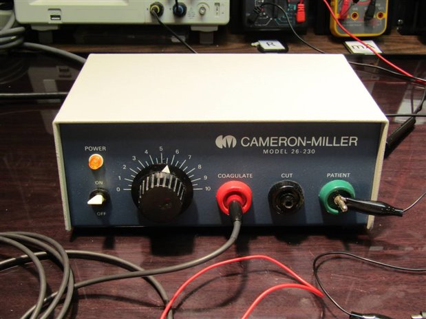
The Electrosurgery unit works by providing a high frequency, in this case about 2.8 MHz, current that is used to cut and coagulate as needed in minor surgeries. This particular unit is a Cameron Miller Model 26-230 and was manufactured a few years ago. I know that it was a few years ago as the circuit uses Vacuum Tube technology and the company address on the unit lacks a ZIP code. I wanted to share the design and construction of it with you as it is a good example of a nice simple design that was built to last.
Here is a picture of the insides:
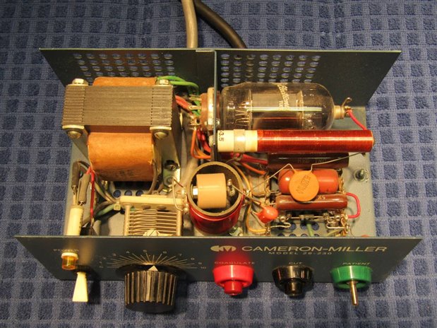
The vacuum tube is a 6GJ5 Beam Power Tube that was more typically used in the Horizontal Deflection Amplifier circuit of 1950s and 1960s area TV Sets. For those of you accustomed to working on transistor based technology the big difference between transistor technology and tube technology is the 1000 Volts on the red wire going to the plate of the tube. In this case the plate connection is the silver button on the top of the tube. The circuit is just an oscillator whose output is coupled to the CUT (Black) output on the front panel through the variable capacitor. The more the capacitance is increased the more current that is available for cutting. The Coagulate ( Red) output is linked to the Cut Output with a 0.001 1000VDC capacitor. This serves to reduce and limit the current of the Coagulate terminal which is used for procedures where cutting is not needed.
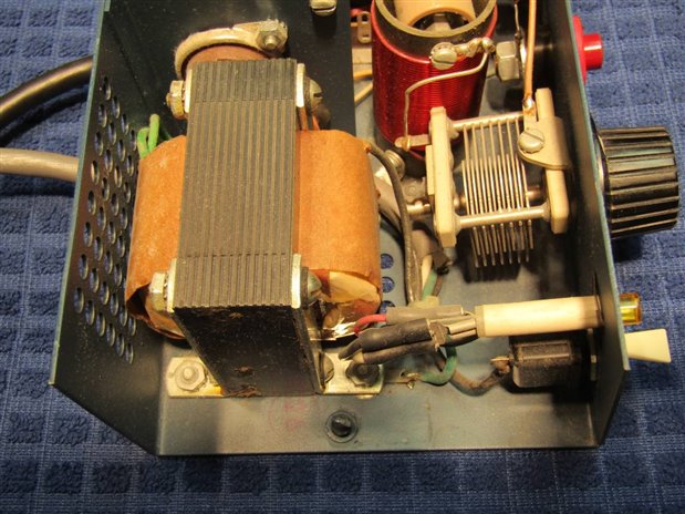
The power supply is a transformer with a 6 volt secondary that is used for the filament of the 6GJ5 tube and a 750 Volt secondary that goes to a full wave bridge rectifier. The bridge diodes are actually silicon types of similar appearance to 1N4007s. The designer of the circuit did not bother to filter the DC output of the bridge leaving it to pulse at 120 Hz. The effect of this is to create an output the has 2.8 MHz pulses with a frequency of 120 Hz.
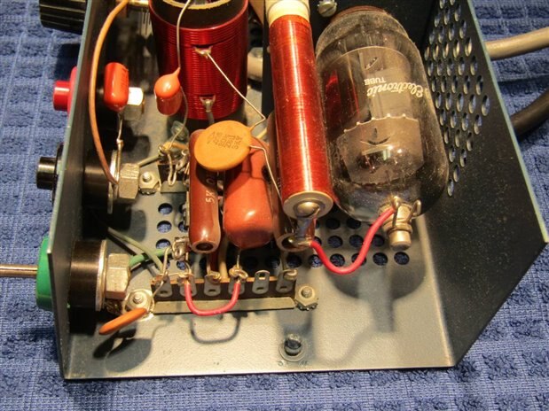
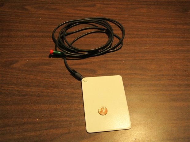
Here is another view inside the unit. The Green Output terminal in the left foreground is marked PATIENT. Yes they have a ground wire that goes out to the patient. It is terminated with an insulated plate 12 cm X 9 cm that is placed under the patient's leg or bottom, outside the clothing. This plate makes a capacitive coupling to the patient and works very well at 2.8 MHz. Here is a picture of the Plate and cable.
You may at this point be asking yourself, "He said it came in for repair so what was wrong with it?" Well, there was nothing wrong with the unit. In 30 years I have never had to fix a single one of these units and I have never had to replace a tube in one of them. The only things I have ever had to work on are the cords that go to the cutting handpiece and the Patient plate. In this case the cord to the handpiece had broken wires where the cord entered the back of the handpiece. I replaced the cord on the handpiece and installed a new banana plug on the end and everything was good as new.
John
Top Comments