


Tonight I have been involved in the diagnosis and repair of a Hybrid Switching/Linear power supply board from a Pelton Crane Validator Plus dental instrument sterilizer. Due to a design flaw in this model sterilizer this is not the first time I have seen this problem. The board is positioned in the sterilizer directly under the water reservoir. If the person filling the water reservoir is careless water drips down onto the board. There is some protection afforded the board by an aluminum plate but experience has shown this protection to be ineffective over time. Here is a picture of the failed power supply board:
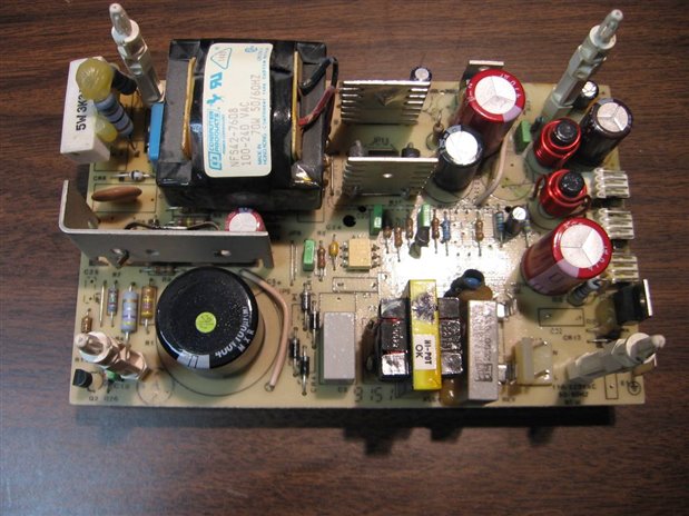
As an overview I will tell you that the 115 VAC attaches to the board on the 2 pin connector in the lower right. The power conversion then progresses in a clockwise direction around the board until the output exits the board on the three white 4 pin angle headers on the right edge. When working properly the board produces +5 volts, +12 volts, and -12 volts with a common ground. This is an OEM board and no information or specifications are provided. It is considered unrepairable by the manufacturer who really wants to sell very expensive replacement boards instead of repairing the ones that fail.
I begin my repair with a very thorough inspection of the board, both top and bottom. During this inspection I am logging anything suspicious that may be part of the problem. This includes any burns to the components or the board, any cracks or hazing to the solder joints, and any signs of previous repair. I will usually do this with a jewelry loupe and a small analog meter with which I can make quick checks on diodes, transistors, and resistors. At the same time as the inspection I am attempting to understand the design of the board and how it might work. There is always a lot of guess work involved in this as I am not an engineer but slowly over the years I have gotten a little better at it. As I mentioned this board has been subjected to water falling on it occasionally over a long period of time. This was evidenced by crystal deposits on the end of the board where the 3 white angle headers are. Here are a couple pictures of the damaged area:
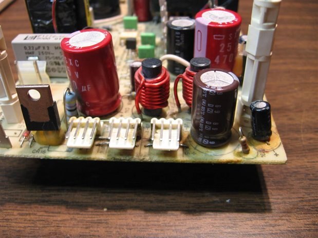

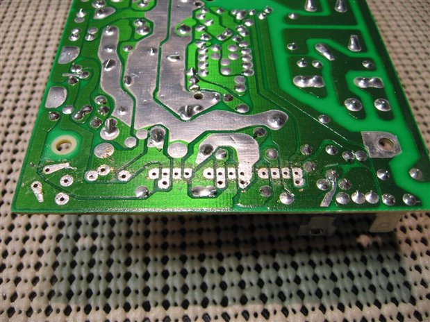
The good news was that the water damage was restricted to the low voltage output end of the board. The solder side of the board was in pristine condition with no signs of water damage. Visual inspection showed that a couple jumper buss wires had been badly corroded and one was open completely. Water had apparently capillaried under two decoupling capacitors in the damage area and they would have to be removed for inspection. This board was able to continue working, probably for years, despite the occasional water contamination because the water was isolated to the low voltage area. If you mix low voltage with water and metal you will get an effect that slowly destroys and eats away the electrode that is at a more positive potential. The small additional current load produced by the resistance in the water and this reaction were never enough to cause a failure. It wasn't until a buss wire became totally broken that the board failed. I began the repair process by removing all components and headers in the water damage area. The headers were cleaned and showed no permanent damage. The positive leads on both of the capacitors were each eaten away and the capacitors would have to be replaced. I was able to find an exact replacement for the 47 uF 50 volt cap but the 1200 uF 16 volt had to be replaced with another value. My options were 1000 uF or 2200 uF. I chose the 2200 uF at 16 volt as I felt it would allow me to err on the side of caution. Here is what the board looked like with the components removed:
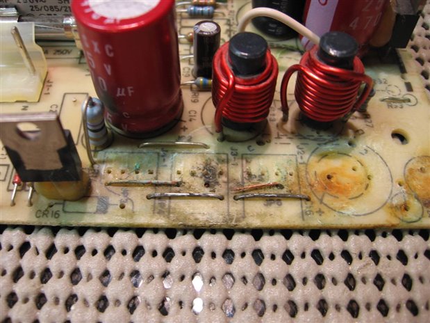
One can clearly see the damage to the buss jumpers and incidentally the green color on the component side of the board is a clear indication of the electrolysis of copper from the wires. The board was cleaned with a wire brush and some solvents. New buss wire was then installed along with the replacement components. With everything installed and looking like new it is time to test the board. To this point I had applied no power to the board so all my work might be in vain if something is wrong with the switching circuitry. I hooked the board up so that my little bread board meters were on the +5 volt and +12 volt outputs. I put an automotive tail light bulb with 500 mA draw at 12 volts across the -12 volt output. The board was then connected to my variac isolated AC supply and the voltage slowly brought up to 115 VAC. Here is what the test setup looked like:
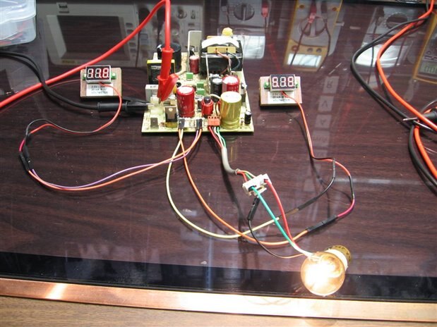
Sorry my shutter was too fast for the LED displays to look good. The power supply board was allowed to run for about an hour. Since I had no specs on the output of the board it was not practical to load up the outputs as I did not want to take the chance of overloading them and damaging the board needlessly. The board was labeled as having been repaired and will be returned to be used in the next Validator Plus sterilizer that comes into the shop with this same problem.
John
Top Comments