element14 Community
element14 Community
    Register Log In
  • Site
  • Search
  • Log In Register
  • Community Hub
    Community Hub
    • What's New on element14
    • Feedback and Support
    • Benefits of Membership
    • Personal Blogs
    • Members Area
    • Achievement Levels
  • Learn
    Learn
    • Ask an Expert
    • eBooks
    • element14 presents
    • Learning Center
    • Tech Spotlight
    • STEM Academy
    • Webinars, Training and Events
    • Learning Groups
  • Technologies
    Technologies
    • 3D Printing
    • FPGA
    • Industrial Automation
    • Internet of Things
    • Power & Energy
    • Sensors
    • Technology Groups
  • Challenges & Projects
    Challenges & Projects
    • Design Challenges
    • element14 presents Projects
    • Project14
    • Arduino Projects
    • Raspberry Pi Projects
    • Project Groups
  • Products
    Products
    • Arduino
    • Avnet & Tria Boards Community
    • Dev Tools
    • Manufacturers
    • Multicomp Pro
    • Product Groups
    • Raspberry Pi
    • RoadTests & Reviews
  • About Us
  • Store
    Store
    • Visit Your Store
    • Choose another store...
      • Europe
      •  Austria (German)
      •  Belgium (Dutch, French)
      •  Bulgaria (Bulgarian)
      •  Czech Republic (Czech)
      •  Denmark (Danish)
      •  Estonia (Estonian)
      •  Finland (Finnish)
      •  France (French)
      •  Germany (German)
      •  Hungary (Hungarian)
      •  Ireland
      •  Israel
      •  Italy (Italian)
      •  Latvia (Latvian)
      •  
      •  Lithuania (Lithuanian)
      •  Netherlands (Dutch)
      •  Norway (Norwegian)
      •  Poland (Polish)
      •  Portugal (Portuguese)
      •  Romania (Romanian)
      •  Russia (Russian)
      •  Slovakia (Slovak)
      •  Slovenia (Slovenian)
      •  Spain (Spanish)
      •  Sweden (Swedish)
      •  Switzerland(German, French)
      •  Turkey (Turkish)
      •  United Kingdom
      • Asia Pacific
      •  Australia
      •  China
      •  Hong Kong
      •  India
      • Japan
      •  Korea (Korean)
      •  Malaysia
      •  New Zealand
      •  Philippines
      •  Singapore
      •  Taiwan
      •  Thailand (Thai)
      • Vietnam
      • Americas
      •  Brazil (Portuguese)
      •  Canada
      •  Mexico (Spanish)
      •  United States
      Can't find the country/region you're looking for? Visit our export site or find a local distributor.
  • Translate
  • Profile
  • Settings
Personal Blogs
  • Community Hub
  • More
Personal Blogs
John Wiltrout's Blog Experiment to Test Tandem LM395 IC Darlington Modules
  • Blog
  • Documents
  • Mentions
  • Sub-Groups
  • Tags
  • More
  • Cancel
  • New
  • Share
  • More
  • Cancel
Group Actions
  • Group RSS
  • More
  • Cancel
Engagement
  • Author Author: jw0752
  • Date Created: 24 Nov 2014 2:40 PM Date Created
  • Views 2509 views
  • Likes 2 likes
  • Comments 23 comments
  • lm395
  • darlington
Related
Recommended

Experiment to Test Tandem LM395 IC Darlington Modules

jw0752
jw0752
24 Nov 2014

A few days ago I posed the question of whether I could add a second Darlington Power transistor in parallel to a commercial circuit that was poorly designed. The response from all of my mentors on E-14 was accurate and to the point. Amongst the many replies was one however that has caused me to take this question one step further and investigate an interesting component IC.


Don Hersey Wrote:


28. Re: Feasability of Adding a Second Parallel Darlington?

image Level 5: Faraday

  Don Hersey Nov 17, 2014 8:06 AM (in response to John Wiltrout)

The pwr on led needs a reversed signal diode in shunt.  LEDs have a reverse breakdown potential of about 6V.  When we parallel bipolars, as an earlier poster stated, we need ballast resistors to minimize current hogging due to the negative tempco of the Qs.


Hanging an emitter follower  on the VR produces an output a diode drop below the regulator output.  As a prior poster noted your Q is operating in the linear mode, probably you should embiggen your heatsink.  When one does that (hangs a Q on a VR) he does increase the ampacity of the regulator.  But he loses the thermal shutdown feature.


The http://www.ti.com.cn/cn/lit/ds/symlink/lm395.pdf LM195 is the transistor for you.  Even though it is bipolar, they can be paralleled freely as they have thermal feedback control on-board.


You can do better than this.  I suggest you read a book or two on operational amplifiers and maybe one on SMPS design


I bought a couple of the LM395T Transistor substitutes that were mentioned by Don and I set up the following experiment. If you want a better picture of the component in question please use Don's link to pull up a Data Sheet from TI. The LM395T is designed to take the place of a Darlington with the added features of thermal, current, and power limit protection.


I used the previous circuit design with a LM317 regulator as the variable driver for a Darlington as the starting point and then I removed the Darlington and substituted (2) LM395T.


Here is a schematic:


image


My plan was to breadboard the circuit and then use the scope to measure the voltage drop across the one Ohm emitter resistors of the LM395s. I would then do a Channel A minus Channel B plot on the Oscilloscope. If the 2 LM395s did actually work together and share the load I should be able to run the output of the LM317 variable regulator from minimum to max with no appreciable change in the A-B Plot. If on the other hand one of the LM395s lagged back and did not share the load we should see a change in A-B with the increase from min to max output.


Here is the completed test setup with the first oscilloscope scan showing the voltage across R-7 and R-8 and the difference plot in the middle.


                  imageimage


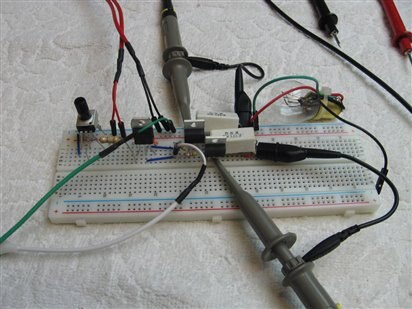
Please remember that this is all about learning and any suggestion that you have for how I could have better set up the experiment or made the setting on the scope will be appreciated. In hind sight it may have been better if I had averaged the channel 1 and 2 readings to clean up the difference plot. I looks like I have 96 mV across the R-8 resistor and 104 mV across the R-7 resistor. The 1 Ohm resistors that I used in the circuit had a "J" code and are therefore rated at 5%. This 5% rating of the resistors along with breadboard connections would lead me to believe that at least at this minimal setting the 2 LM395s were sharing the load. This minimum setting can be the most difficult for the components under test. Since nearly all of our 20 Volts is across the LM395s and we are showing a current of 100 mA the LM395s are each required to dissipate approximately 2 Watts of power. As you can see I have them in free air on the breadboard. Not having learned, after 50 plus years in electronics, not to touch hot things I have a minor red mark on the end of my finger in the shape of a TO-220 case.


The next step is to slowly turn up the voltage of the LM317 and watch the voltages across R-7 and R-8 as well as the difference plot. Here is the final view of the circuit and the oscilloscope plot when the LM317 was at full voltage.


                imageimage


I like to use light bulbs to load my test circuits, in most cases, as I have a visual feedback of what is going on. From the point of view of linearity this is of course not the best idea. Bulbs start off with low impedance and then increase as they heat up. The scope indicated that both of the LM395s shared load as the voltage of the LM317 was increased. I did note that the channel 1 which was reading higher than channel 2 at the minimum by 8mV had changed places and was reading 72 mV lower than channel 2 at the max setting. I am not sure what this would indicate, perhaps there is an optimal input voltage cross over point at which the two LM395 would best work together. Throughout this experiment I have talked about turning up the voltage of the LM317 to drive the LM395s. What this has actually been doing is increasing the base currents in the LM395s as they are current controlled devices and I want to make sure I didn't give the impression that they were voltage controlled. Since this test was basically a meet and greet between the LM395 and myself and I have no immediate application for it my curiosity is satisfied at this point that the LM395 can indeed be used in tandem and would work well in the application to which Don Hersey recommended it.

  • Sign in to reply

Top Comments

  • D_Hersey
    D_Hersey over 11 years ago +1
    I'm thrilled that you tried my suggestion! IIRC these were developed by Widlar et al at the same time as other Linear Monolithic devices such as voltage regulators of the day. It uses the same thermal…
  • jw0752
    jw0752 over 11 years ago in reply to mcb1 +1
    Hi Mark, I broke the Old Dog New Trick mode. Today I made a more sensible way to test. See new blog post. John
  • shabaz
    shabaz over 11 years ago in reply to Problemchild +1
    It is like PP3 battery testing Did the creators of the PP3 standard put the connections on one side to make then easier to lick?
Parents
  • shabaz
    shabaz over 11 years ago

    I'd not heard of this device before, but such a bullet-proof transistor replacement seems very interesting. Thanks for the investigation!

    • Cancel
    • Vote Up 0 Vote Down
    • Sign in to reply
    • More
    • Cancel
  • jw0752
    jw0752 over 11 years ago in reply to shabaz

    Hi Shabaz, Always good to have you looking over my shoulder. I tried to locate the LM195 that Don originally mentioned but none of my suppliers here in USA had it. The LM395T was available and may be the successor to the LM195. The spec sheet that came with the LM395 gave a max Ids as 2.2A and Vds as 36 volts. The Data sheet that was available may be a little out of date.

    John

    • Cancel
    • Vote Up 0 Vote Down
    • Sign in to reply
    • More
    • Cancel
  • mcb1
    mcb1 over 11 years ago in reply to jw0752

    John

    We are all looking over your shoulder, trying not to snigger when you discovered the hot TO220 ... like we've never done that before .image


    I must say you are very brave trying to pass a reasonable amount of current through your breadboard.


    Mark

    • Cancel
    • Vote Up 0 Vote Down
    • Sign in to reply
    • More
    • Cancel
  • shabaz
    shabaz over 11 years ago in reply to jw0752

    Hi John,


    I too spotted Farnell only had the '395 version, added a few to the basket, I think they will come in handy (I don't have many (any) power BJTs currently. The datasheet was old, but it is impressive that a part designed so long ago still has enough uses that it is still manufactured, like the 555.

    Anyway, as you know, we like old parts : )

    • Cancel
    • Vote Up 0 Vote Down
    • Sign in to reply
    • More
    • Cancel
  • jw0752
    jw0752 over 11 years ago in reply to mcb1

    Hi Mark, The real wonder to me is that, having discovered that "they" get hot years and years ago, I haven't adopted a more sensible way to test them than just grabbing them. I will have to work on that. I do it because my curiosity about the temperature can't wait and I really have no better way to quickly ascertain it. What we need is a new tool, a TO-220 size clip on thermometer. As far as the current and the breadboard goes I am, as we say up north here, walking on thin ice. As I have just gotten into breadboarding in the last couple years most of my boards are fairly new which helps. I also run multiple parallel wires and jumpers when possible and finally I try to design my tests, that need higher current, to be short enough so that the metal of the clips do not have time to heat up and loose their temper. So far I have been lucky with no Smoke or Fire.

    John

    • Cancel
    • Vote Up 0 Vote Down
    • Sign in to reply
    • More
    • Cancel
  • mcb1
    mcb1 over 11 years ago in reply to jw0752

    I haven't adopted a more sensible way to test them than just grabbing them

    See it goes to show that you can't teach an old dog new tricks.image


    It becomes worse if you are used to touching the transistors for heat, and then go and repeat the technique on a valve based equipment, and forget that its MUCH higher voltage ... as one chap did a long time ago.


    Mark

    • Cancel
    • Vote Up 0 Vote Down
    • Sign in to reply
    • More
    • Cancel
Comment
  • mcb1
    mcb1 over 11 years ago in reply to jw0752

    I haven't adopted a more sensible way to test them than just grabbing them

    See it goes to show that you can't teach an old dog new tricks.image


    It becomes worse if you are used to touching the transistors for heat, and then go and repeat the technique on a valve based equipment, and forget that its MUCH higher voltage ... as one chap did a long time ago.


    Mark

    • Cancel
    • Vote Up 0 Vote Down
    • Sign in to reply
    • More
    • Cancel
Children
  • jw0752
    jw0752 over 11 years ago in reply to mcb1

    Hi Mark, I broke the Old Dog New Trick mode. Today I made a more sensible way to test. See new blog post.

    John

    • Cancel
    • Vote Up +1 Vote Down
    • Sign in to reply
    • More
    • Cancel
  • mcb1
    mcb1 over 11 years ago in reply to jw0752

    Well done

    http://www.element14.com/community/people/jw0752/blog/2014/11/26/new-gadget--no-more-to-220-finger-burns#comment-46725

    • Cancel
    • Vote Up 0 Vote Down
    • Sign in to reply
    • More
    • Cancel
element14 Community

element14 is the first online community specifically for engineers. Connect with your peers and get expert answers to your questions.

  • Members
  • Learn
  • Technologies
  • Challenges & Projects
  • Products
  • Store
  • About Us
  • Feedback & Support
  • FAQs
  • Terms of Use
  • Privacy Policy
  • Legal and Copyright Notices
  • Sitemap
  • Cookies

An Avnet Company © 2026 Premier Farnell Limited. All Rights Reserved.

Premier Farnell Ltd, registered in England and Wales (no 00876412), registered office: Farnell House, Forge Lane, Leeds LS12 2NE.

ICP 备案号 10220084.

Follow element14

  • X
  • Facebook
  • linkedin
  • YouTube