


The other day I came across this interesting circuit board from a piece of Medical Equipment.

My interest was immediately caught by the LMD 18200 H-Bridges in the upper left corner. I checked the part number out on Newark's site to see if they were still current. I find it more fun to investigate a part if it is still available. In this case an improved version is still being manufactured and is available. Here is the listing from Newark:
http://www.newark.com/texas-instruments/lmd18200t-nopb/motor-controller-half-bridge-6a/dp/41K2745
While I am at it, here is also the link to the Data Sheet.
http://www.farnell.com/datasheets/1771446.pdf
Tonight I am going to go through the salvage, preparation and a simple experiment with this device.
Here is a closer look at the component still mounted to the board.

The salvage of the component from the board was a bit of a challenge. Caution has to be taken not to damage the part and with eleven legs to remove it does not cooperate. In this case I tried to use the heat gun to melt all the solder points at the same time but there was too much heat dissipation in the component. Next I tried to heat and solder vacuum the individual legs. This removed most of the solder but still not enough. My next approach was to put the solder back on the front legs and lift them one at a time as I heated the solder with the iron from the back side of the board. Once the front legs were free I went to work on the 5 back legs and finally was able to free the component. Now that I had the proper technique down the second LMD 18200 came out more easily. In a couple instances, in the past, I have gone so far as to cut the board with a drehmel so that the individual pads could be removed from a desirable component. Fortunately this wasn't necessary this time.
After the chip was free I soldered bread board wires to each of the eleven legs and attached the IC to a piece of aluminum so I would not have to worry about heat during my experiment.


For the experiment I am going to hook the H-Bridge up as described on page 9 of the data sheet under "Simple, locked anti-phase PWM". The H-Bridge is going to drive a 30 volt DC motor, that I salvaged from a Kodak printer. I have attached a cardboard wheel with a spiral drawn with a magic marker to make it easier to see direction and speed of the motor. While the LMD 18200 can control up to 55 volts and 3 amps, I will use 20 volts for the experiment as I want the motor well controlled at low speeds so that my cheap video camera can capture the movement. When it isn't under load and is stopped by the 50% duty cycle my motor draws about 60 mA. The current draw increases to over 100 mA as the speed increases. I probably would not have needed the heat sink but better safe than sorry.
Here is a picture of the H-Bridge wired up for the experiment.
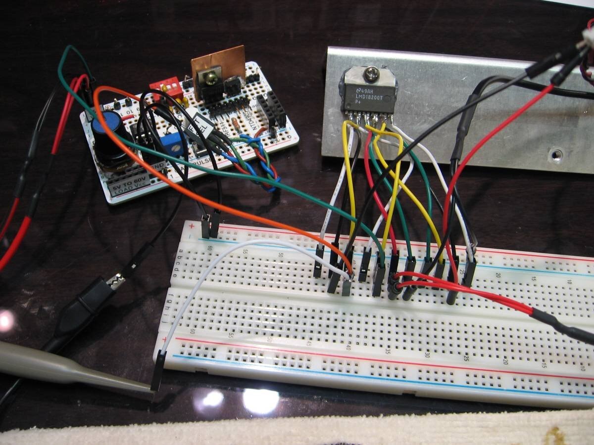
Thanks to a previous project (Pulse Width Modulation Test Jig ) this experiment is greatly simplified as I already have a good source of PMW that can be varied between 5% and 95% duty cycle. Here is how it will work. The PWM test jig is being powered with 12 volts as recommended in the data sheet. We are supplying 20 volts between the Vcc (pin 6) and ground (pin 7) of the LMD 18200. The motor is connected between the outputs of the LMD 18200 (pins 2 & 10). The usual PWM input (pin 5) is tied High so that the maximum voltage (a little less than 20 volts) is applied through the bridge to the motor. The PWM signal, sourced from the PWM Test Jig, is input to the direction control (pin 3) of the LMD18200. For this simple experiment this is all that is necessary. While the LMD 18200 has a lot more capabilities such as RPM, Torque, and Current control and feedback we're are just going for Forward - Stop - Reverse at this time. The PWM signal on the direction input (pin 3) causes the LMD 18200 to feed forward and reverse voltage alternately to the motor. These individual pulses are equal and opposite if the duty cycle is 50%. The motor does not move in this situation. I did note that it made a noise at the fundamental frequency of the PWM. However, if the PWM signal is moved either direction off of 50% duty cycle the motor receives a net voltage in either the forward or reverse direction and starts to spin. When the duty cycle approaches 0% or 100% the motor is receiving full available voltage in that direction. I have the scope monitoring the PWM signal so that we can watch how the change in the duty cycle causes the motor to react. The motor is positioned in front of the scope so the direction and speed can be compared to the duty cycle of the PWM. Please check out the short video.
Building with electronics is similar to building with Legos. There are a lot of different little components that are like different shaped Legos. Experiments like this one give me a chance to become familiar with the shape (figurative) and function of components that are available in the electronic universe just as familiarity with the different shaped Lego blocks allows one to be more creative in the Lego universe. The next step in this experiment will be to build the other test applications suggested in the Data sheet. When I am done my notes and pictures will be put in a binder where they will be available if the need to build with the H-Bridge arises.
John
.
Top Comments