element14 Community
element14 Community
    Register Log In
  • Site
  • Search
  • Log In Register
  • Community Hub
    Community Hub
    • What's New on element14
    • Feedback and Support
    • Benefits of Membership
    • Personal Blogs
    • Members Area
    • Achievement Levels
  • Learn
    Learn
    • Ask an Expert
    • eBooks
    • element14 presents
    • Learning Center
    • Tech Spotlight
    • STEM Academy
    • Webinars, Training and Events
    • Learning Groups
  • Technologies
    Technologies
    • 3D Printing
    • FPGA
    • Industrial Automation
    • Internet of Things
    • Power & Energy
    • Sensors
    • Technology Groups
  • Challenges & Projects
    Challenges & Projects
    • Design Challenges
    • element14 presents Projects
    • Project14
    • Arduino Projects
    • Raspberry Pi Projects
    • Project Groups
  • Products
    Products
    • Arduino
    • Avnet Boards Community
    • Dev Tools
    • Manufacturers
    • Multicomp Pro
    • Product Groups
    • Raspberry Pi
    • RoadTests & Reviews
  • Store
    Store
    • Visit Your Store
    • Choose another store...
      • Europe
      •  Austria (German)
      •  Belgium (Dutch, French)
      •  Bulgaria (Bulgarian)
      •  Czech Republic (Czech)
      •  Denmark (Danish)
      •  Estonia (Estonian)
      •  Finland (Finnish)
      •  France (French)
      •  Germany (German)
      •  Hungary (Hungarian)
      •  Ireland
      •  Israel
      •  Italy (Italian)
      •  Latvia (Latvian)
      •  
      •  Lithuania (Lithuanian)
      •  Netherlands (Dutch)
      •  Norway (Norwegian)
      •  Poland (Polish)
      •  Portugal (Portuguese)
      •  Romania (Romanian)
      •  Russia (Russian)
      •  Slovakia (Slovak)
      •  Slovenia (Slovenian)
      •  Spain (Spanish)
      •  Sweden (Swedish)
      •  Switzerland(German, French)
      •  Turkey (Turkish)
      •  United Kingdom
      • Asia Pacific
      •  Australia
      •  China
      •  Hong Kong
      •  India
      •  Korea (Korean)
      •  Malaysia
      •  New Zealand
      •  Philippines
      •  Singapore
      •  Taiwan
      •  Thailand (Thai)
      • Americas
      •  Brazil (Portuguese)
      •  Canada
      •  Mexico (Spanish)
      •  United States
      Can't find the country/region you're looking for? Visit our export site or find a local distributor.
  • Translate
  • Profile
  • Settings
Personal Blogs
  • Community Hub
  • More
Personal Blogs
John Wiltrout's Blog Fun with an Old X-Ray Display Board
  • Blog
  • Documents
  • Mentions
  • Sub-Groups
  • Tags
  • More
  • Cancel
  • New
  • Share
  • More
  • Cancel
Group Actions
  • Group RSS
  • More
  • Cancel
Engagement
  • Author Author: jw0752
  • Date Created: 29 Apr 2015 6:08 AM Date Created
  • Views 425 views
  • Likes 2 likes
  • Comments 5 comments
  • analog_to_digital
  • digital_voltmeter
  • ca3162e
  • reverse_engineering
Related
Recommended

Fun with an Old X-Ray Display Board

jw0752
jw0752
29 Apr 2015

One of the things that I enjoy doing is taking an old unused circuit board and reverse engineering it to see how it works. Today I have a time display board from a Dental X-Ray machine that my son gave me. The typical old dental x-ray machine dispenses its radiation in short bursts of 1/120 of a second. This is caused by feeding AC voltage to the primary transformer of the tube head. The X-Ray tube itself is actually a high voltage vacuum tube diode with a plate of tungsten as a target on the cathode of the tube. The electrons striking the tungsten plate cause the orbital electrons of the tungsten to transition between energy levels and emit x-rays. While the transformer produces 70 kV of AC voltage across the x-ray tube, the tube will only conduct during half the cycle. Thus we get 1/120 of a second bursts of x-rays from the tube head. The Timer Display Board that was being explored today has a display that would have indicated how many of these 1/120 second pulses of x-rays were being delivered to the patient.


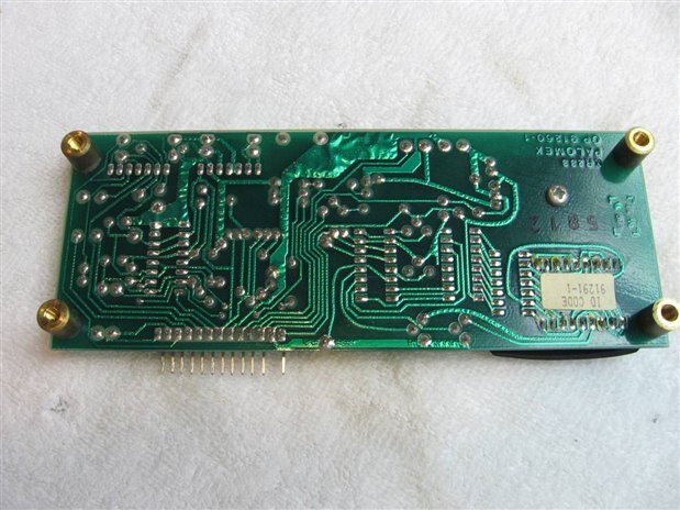
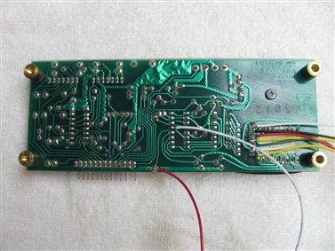
Front and back views of the board:


imageimage


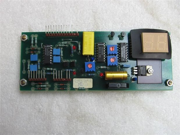
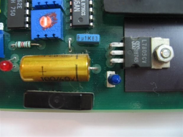
The first approach to reverse engineering is to identify some of the major parts and follow traces to see what is connected to what. The components that first caught my attention were the Bridge Rectifier, a Ripple smoothing Capacitor, and a 7805 voltage regulator. These are in the lower right hand corner of the board. See the close up below this paragraph. While I did not know what AC voltage was needed for powering the board the 7805 regulator would be my guide. Usually the input voltage to a linear voltage regulator must be at least 2 to 3 volts higher than the output. Since the output in this case is 5 volts I would start with 5 volts AC input to the board and raise it slowly until my input voltage on the 7805 measured 8 volts DC. I was rewarded by seeing the two 7 segment displays light up with zeros.


imageimage


My attention next turned to the 2 16 pin DIP ICs just to the left of the dual seven segment display. The first one, a SN7446AN was a BCD to Seven Segment Decoder/ Driver. The second one, a CA3162E turned out to be a 3 Digit Analog to Digital display converter. The Data Sheet was down loaded and looked over. Here is a link to the data sheet incase you want to check it out.


http://datasheet.octopart.com/CA3162E-Intersil-datasheet-36279.pdf


I studied the pinouts on the CA3162E and how they tied into the rest of the circuit. Once the input of the A/D converter was identified it was decided to put a small voltage on it to see how it affected the read out of the display. After making a voltage divider with resistors 0.72 volts DC was put on the input. To my delight the display shone back 72. Next the voltage was turned up to 0.99 volts above which point the display went blank. Once the voltage was back at 0.99 volts the display was back in sync with the input.


It now occurred to me that the data sheet had indicated that the CA3162E was actually a 3 digit AD converter. When the traces on the board were checked, sure enough pin 5 of the CA3162E, the Least Significant Digit, was not connected. The other two, MSD and NSD were connected to PNP transistors which in turn would apply +5 volts to the common cathodes of the individual display digits. The CA3162 was strobing the display with the series of outputs and turning on individual seven segment displays for the number that belonged in that position.


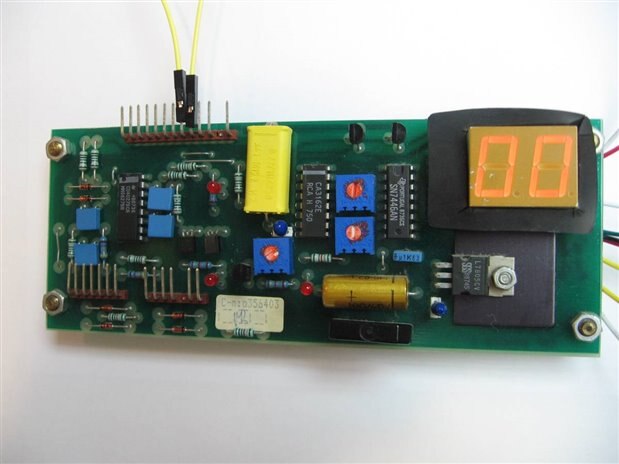
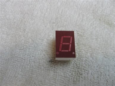
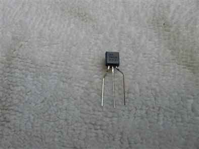
The electronic Frankenstein in me made me ask;  Can the third digit be added? A trip to the parts supply bins was successful. All that was needed was a common cathode seven segment display and a PNP control transistor. See pictures below. Wires were soldered to the circuit board. The pull down wires from the SN7446AN were needed as well as a +5 volt supply, the common ground, and an input wire to the AD converter. The data sheet for the SN7446AN was used to identify the segments associated with each wire. Here is the board after the extension wires were attached.


imageimageimage


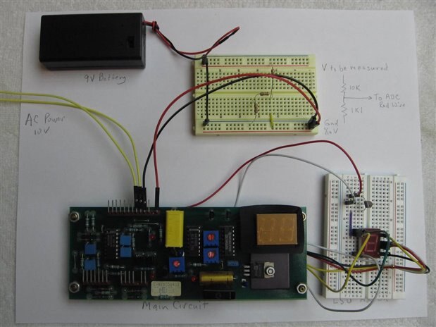
The third digit and the switching transistor were assembled on one small bread board and a 10:1 resistive voltage divider for the input to the AD converter was assembled on a second bread board. An old 9 volt battery was attached to the voltage divider and 1/10 of its voltage would be seen by the AD converter. The Fluke would give me an accurate reference. Here is the result:


imageimage


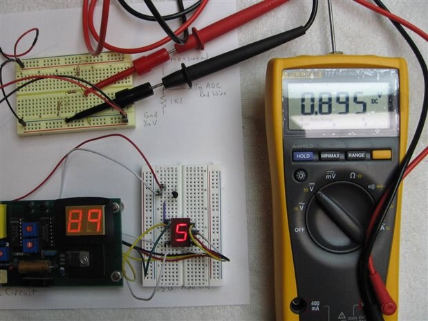
There are 2 blue 5K trim pots between the CA3162 and the SN7446. The one on the bottom is used to set zero on the display. The upper trim pot is the gain and can be used to calibrate the ADC to the actual input voltage. Since the board did not have a Least Significant Digit until today it was necessary to tweak both trim pots slightly.


This board could now be used in an application where voltage needed to be measured to the millivolt level. The three decimal points are not used at this time but they are available so the board input could be switched using different voltage dividers to provide ranges of 0 to 0.999 volts, 0 to 9.99 volts, or 0 to 99.9 volts.


At this point I do not know if or how it will be used. The board will be further explored as I still don't know what the purpose for the Flip Flop chip on the left side of the board. Sometimes boards like this are just a minor subassembly for the larger system and do not contain enough structure to stand on their own. The little ADC with its own power supply was a nice surprise.


John 

  • Sign in to reply

Top Comments

  • DAB
    DAB over 10 years ago in reply to jw0752 +1
    Yeah, I concede that I have to grow old, but I refuse to concede that I must grow up. DAB
  • DAB
    DAB over 10 years ago in reply to jw0752

    Yeah, I concede that I have to grow old, but I refuse to concede that I must grow up.


    DAB

    • Cancel
    • Vote Up +1 Vote Down
    • Sign in to reply
    • More
    • Cancel
  • jw0752
    jw0752 over 10 years ago in reply to DAB

    Thanks Donald,

    I am always glad to find some kids my own age, like you, to play with.

    John

    • Cancel
    • Vote Up 0 Vote Down
    • Sign in to reply
    • More
    • Cancel
  • jw0752
    jw0752 over 10 years ago in reply to shabaz

    Hi Shabaz,

    The yellow capacitor in question is an integrating capacitor between pin 12 of the CA3162 and 5 volts +. I will have to study up as I do not know the purpose of an integrating capacitor. The CD4027BCN Flip Flop Chip does not seem to be tied into the ADC at all. I suspect it is part of another circuit that is off board. One of these nights I will investigate it further. The two little transistors at its side are just common 2N3904 NPN BJTs. Thanks for reading my blog. I always appreciate your input.

    John

    • Cancel
    • Vote Up 0 Vote Down
    • Sign in to reply
    • More
    • Cancel
  • DAB
    DAB over 10 years ago

    Nice blog John,


    It is nice seeing components from my older days seeing the light and still working.


    Well done.


    DAB

    • Cancel
    • Vote Up 0 Vote Down
    • Sign in to reply
    • More
    • Cancel
  • shabaz
    shabaz over 10 years ago

    Hi John,


    Thanks for the enjoyable blog post! It was a very interesting read, and very cool that you got an extra digit for mV measurement and could be trimmed for accuracy!!

    I'm wondering if the flip flops are used to switch an analog voltage to the yellow capacitor (i.e. like some sort of integrator for all the bursts of radiation), since the two transistors on their sides could perhaps be doing some analog switching. Are they FETs from the part number perhaps?

    • Cancel
    • Vote Up 0 Vote Down
    • Sign in to reply
    • More
    • Cancel
element14 Community

element14 is the first online community specifically for engineers. Connect with your peers and get expert answers to your questions.

  • Members
  • Learn
  • Technologies
  • Challenges & Projects
  • Products
  • Store
  • About Us
  • Feedback & Support
  • FAQs
  • Terms of Use
  • Privacy Policy
  • Legal and Copyright Notices
  • Sitemap
  • Cookies

An Avnet Company © 2025 Premier Farnell Limited. All Rights Reserved.

Premier Farnell Ltd, registered in England and Wales (no 00876412), registered office: Farnell House, Forge Lane, Leeds LS12 2NE.

ICP 备案号 10220084.

Follow element14

  • X
  • Facebook
  • linkedin
  • YouTube