


A while back I explored the Ideal Bridge available using the LT 4320 Controller and 4 N Channel MOSFETs.
I also built a two channel linear bench supply using some Chinese Kits.
https://www.element14.com/community/people/jw0752/blog/2017/02/11/oh-no-not-another-power-supply
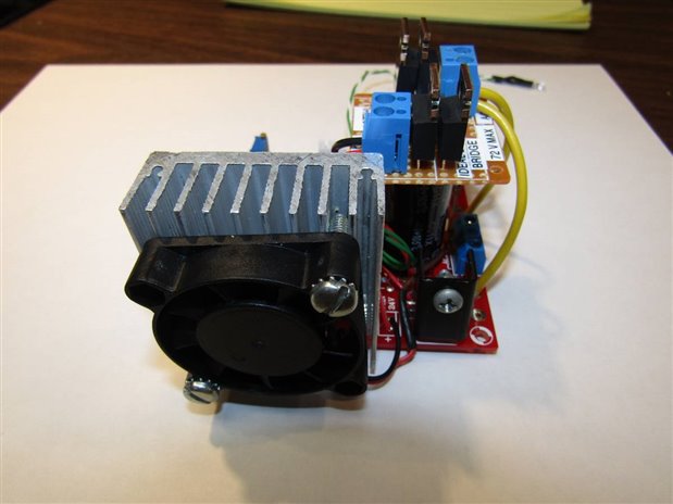
In this blog I will explore the results when I built another module with the Chinese Power Supply Kit but this time instead of using the 1N5408 Diodes supplied I substituted the LT 4320 Controller with 4 MOSFETs. Here are some pictures of the completed Module.

The small board in the upper left is the LT 4320 with the MOSFETs. The Yellow wires supply the AC voltage and the RED and Black are the rectified output back to the board. The small auxiliary board in the lower left is the fan controller which supplies about 11 volts to the 24 volt fan at room temperature and increases the voltage to the full 24 volts as the heat sink approaches 100 C.

The Red lead with the black coupler is the 12 volt supply to the meter circuitry.
The nice Radio Shack CPU heat sink that I used on the first two modules was not available any more so I had to use this less impressive but still adequate sink. The fan for this sink came at 24 volts instead of the previous 12 volts so the fan control had to be modified to make the adjustment. Since 24 volts was so close to the max raw voltage from the unregulated supply I used it directly instead of placing a regulator in the circuit.
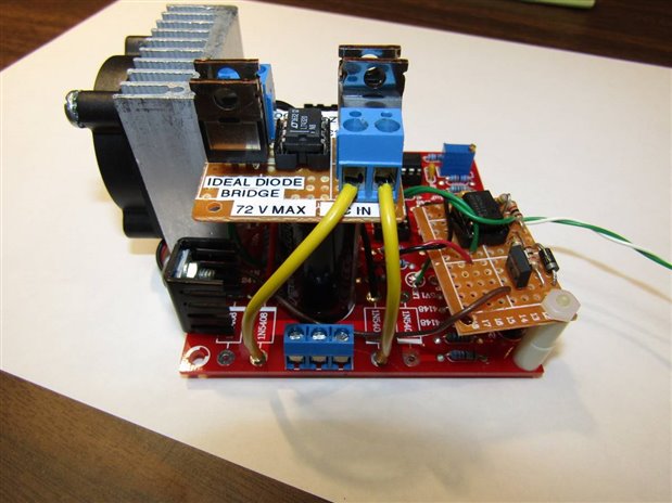
Here is the final side view of the module. The next step was to remove one of the Diode Modules from the Linear Supply and install the LT4320 version.

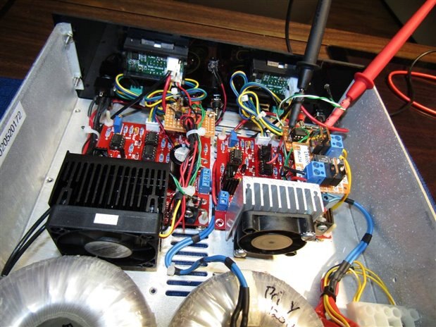
The meter probes are looking at the voltage to the fan as the heat sink rises in temperature under a 36 Watt dissipation.
This is just the view from the back.
The goal of this experiment was to see what the difference would be between a channel using the LT4320 as opposed to the 1N5408 Diodes. Keep in mind the supply has identical Toroid Transformers and support controls for each channel. It turn out that the LT4320 side had a Max 27.6 Volts and the Diode side had 25.7 Volts. Besides this unloaded voltage difference at the top the load capability also showed the same differential. For example I turned both channels to their max output and then load each channel with a 2 amp load. The LT 4320 side dropped to 22 volts before it could support 2 amps. The Diode side dropped to 20.4 volts before it could support the 2 amp load. Even under a 3 amp load which is the max for this supply the MOSFETs ran very close to room temperature. While I like the LT4320 from a standpoint of improved efficiency and sophistication the improvement is probably not enough to justify its use in most cases.
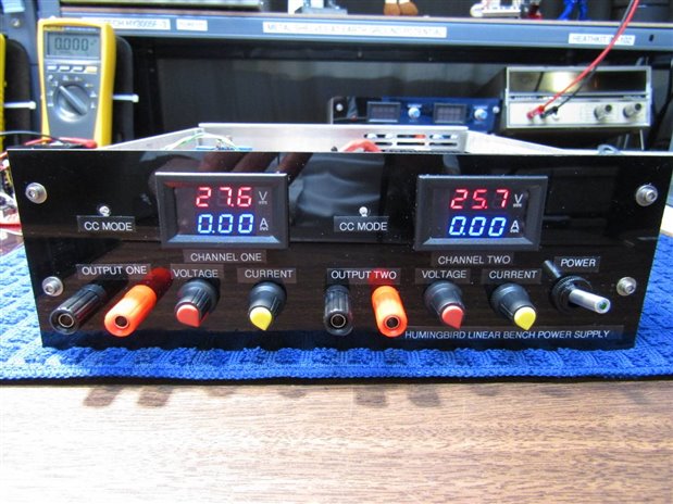
Picture showing the no load difference between the two channels.
John
Top Comments