element14 Community
element14 Community
    Register Log In
  • Site
  • Search
  • Log In Register
  • Community Hub
    Community Hub
    • What's New on element14
    • Feedback and Support
    • Benefits of Membership
    • Personal Blogs
    • Members Area
    • Achievement Levels
  • Learn
    Learn
    • Ask an Expert
    • eBooks
    • element14 presents
    • Learning Center
    • Tech Spotlight
    • STEM Academy
    • Webinars, Training and Events
    • Learning Groups
  • Technologies
    Technologies
    • 3D Printing
    • FPGA
    • Industrial Automation
    • Internet of Things
    • Power & Energy
    • Sensors
    • Technology Groups
  • Challenges & Projects
    Challenges & Projects
    • Design Challenges
    • element14 presents Projects
    • Project14
    • Arduino Projects
    • Raspberry Pi Projects
    • Project Groups
  • Products
    Products
    • Arduino
    • Avnet & Tria Boards Community
    • Dev Tools
    • Manufacturers
    • Multicomp Pro
    • Product Groups
    • Raspberry Pi
    • RoadTests & Reviews
  • About Us
  • Store
    Store
    • Visit Your Store
    • Choose another store...
      • Europe
      •  Austria (German)
      •  Belgium (Dutch, French)
      •  Bulgaria (Bulgarian)
      •  Czech Republic (Czech)
      •  Denmark (Danish)
      •  Estonia (Estonian)
      •  Finland (Finnish)
      •  France (French)
      •  Germany (German)
      •  Hungary (Hungarian)
      •  Ireland
      •  Israel
      •  Italy (Italian)
      •  Latvia (Latvian)
      •  
      •  Lithuania (Lithuanian)
      •  Netherlands (Dutch)
      •  Norway (Norwegian)
      •  Poland (Polish)
      •  Portugal (Portuguese)
      •  Romania (Romanian)
      •  Russia (Russian)
      •  Slovakia (Slovak)
      •  Slovenia (Slovenian)
      •  Spain (Spanish)
      •  Sweden (Swedish)
      •  Switzerland(German, French)
      •  Turkey (Turkish)
      •  United Kingdom
      • Asia Pacific
      •  Australia
      •  China
      •  Hong Kong
      •  India
      •  Korea (Korean)
      •  Malaysia
      •  New Zealand
      •  Philippines
      •  Singapore
      •  Taiwan
      •  Thailand (Thai)
      • Americas
      •  Brazil (Portuguese)
      •  Canada
      •  Mexico (Spanish)
      •  United States
      Can't find the country/region you're looking for? Visit our export site or find a local distributor.
  • Translate
  • Profile
  • Settings
Personal Blogs
  • Community Hub
  • More
Personal Blogs
John Wiltrout's Blog Process Duration Timer (Final Chapter) Assembly and Testing
  • Blog
  • Documents
  • Mentions
  • Sub-Groups
  • Tags
  • More
  • Cancel
  • New
  • Share
  • More
  • Cancel
Group Actions
  • Group RSS
  • More
  • Cancel
Engagement
  • Author Author: jw0752
  • Date Created: 8 Aug 2017 5:23 AM Date Created
  • Views 4069 views
  • Likes 10 likes
  • Comments 19 comments
  • diytestequipch
  • process duration timer
Related
Recommended

Process Duration Timer (Final Chapter) Assembly and Testing

jw0752
jw0752
8 Aug 2017

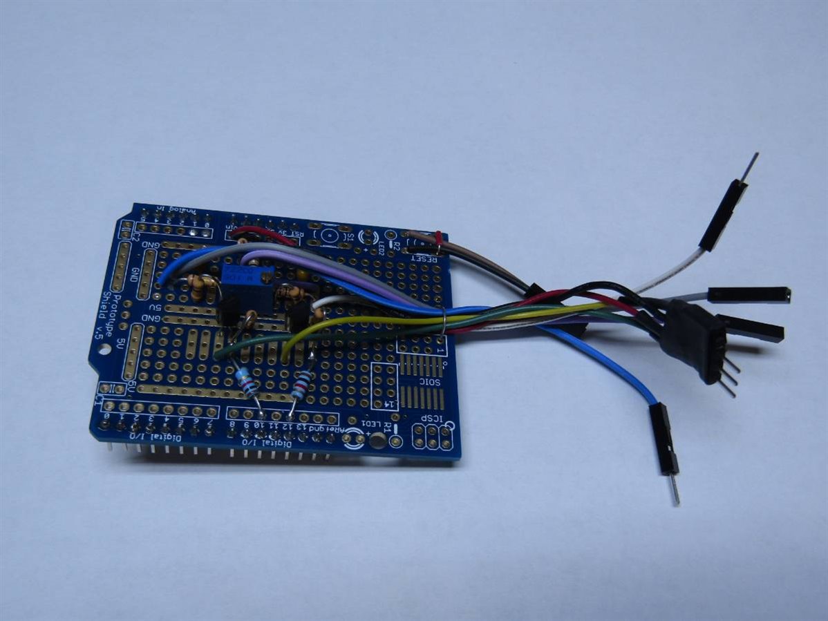
If you have followed the previous 3 posts about this project you know that we are at the point where the rubber meets the road. I have now put the interface circuits, that were previously on bread boards, on to an Arduino shield board. The shield will make all of the necessary connections to the Arduino. The connections from the interface board to the rest of the circuit are being assembled so that I will be able to easily disconnect and remove the interface board for modification or service if necessary. Here is a picture of the completed interface board:


image


image


I have also improved the schematics for the interfaces and included the hookup wire color that is being used to assist me if I have to troubleshoot the unit in the future.


image


image


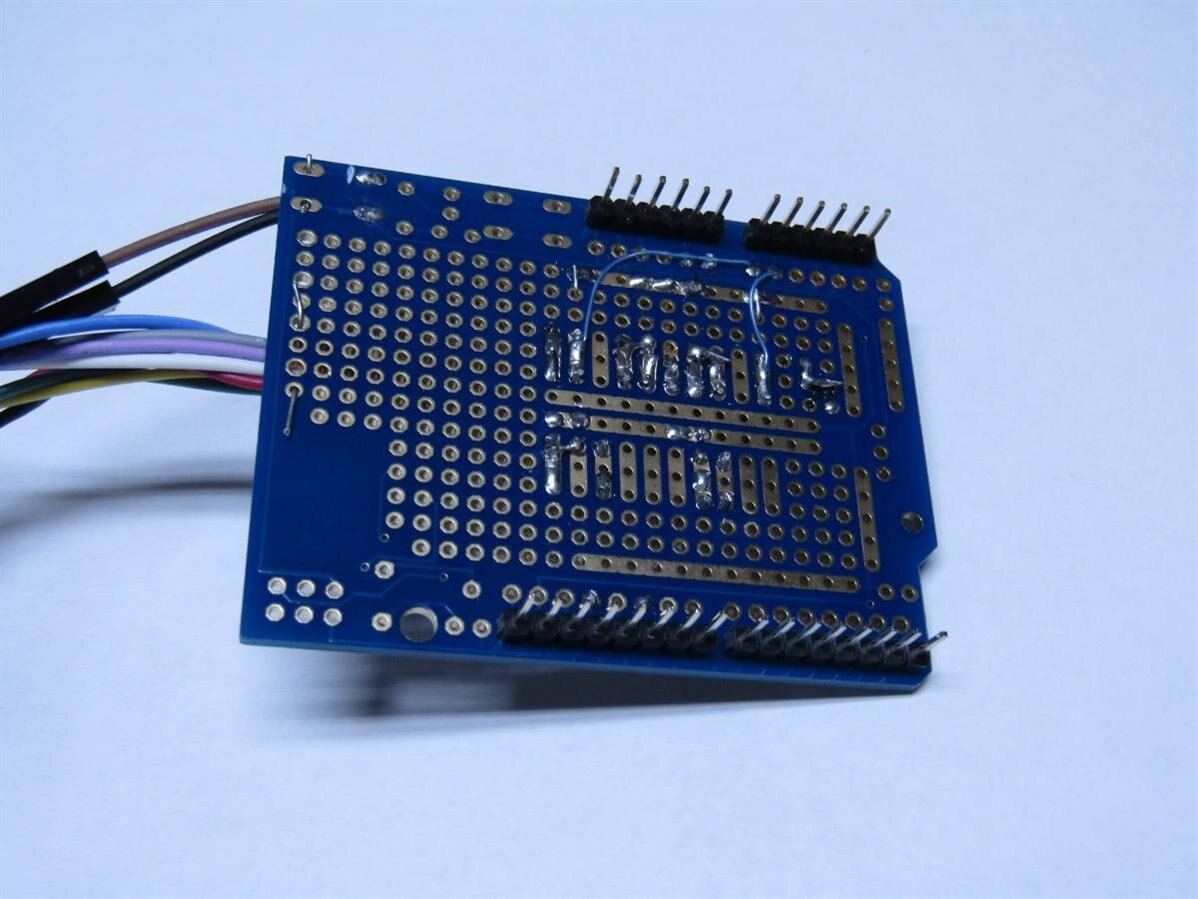
As mentioned before both of these circuits have been installed on the Arduino Shield board.


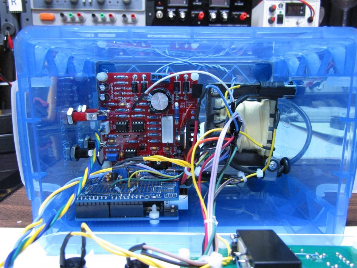
For the power hookup which brings 9 volts to the Arduino I have made up a polarized connector using board headers. The rest of the connections to the peripheral circuit are going to be made with Male-Female bread board wires which I have cut in half to produce a color coded connection (see schematics for colors used). While these wires are really quite small gauge they are more than adequate for this low current application. Half of the cut bread board wire is attached to the interface board and the other half is attached to the appropriate point on the peripheral circuits. I always put the female ends on the wires that may be powered when disconnected so that they can not short to other wires or components. Here are a couple pictures of the unit with and without the interface board installed.


image


image


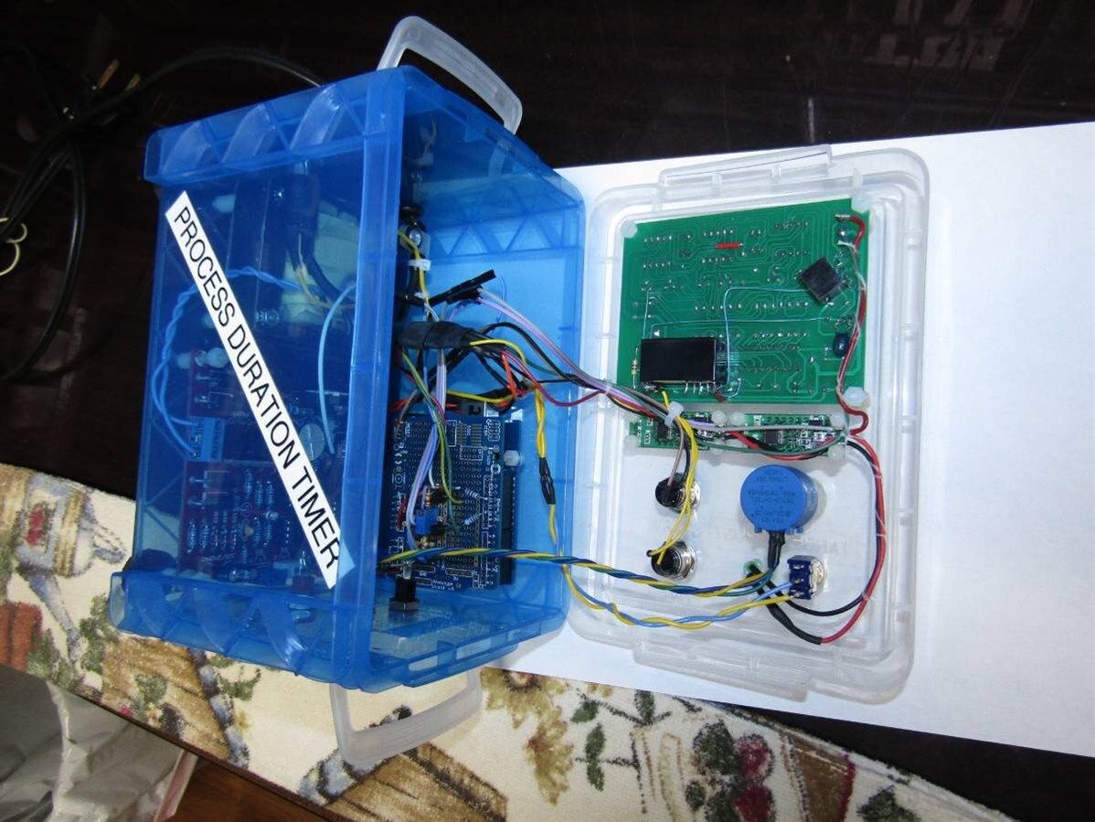
With projects like this I like to layout the wiring harness so that I can open the unit and have access to the circuits without having to stress the wires or their connections. To do this I make sure that the wires all pass over the same edge so that the cover can be laid back as in this photo:


image


This point in building a project is always the most nerve wracking for me as I am about to turn the unit on for the first time. Though I have checked every connection there is always a chance that it may not work or worse yet there may be smoke and fire. If that happens it would force me into skipping sleeping tonight so that I can get to the bottom of the problem. Fortunately I have been lucky this time and everything comes on and works as planned. I have made a short video of the first tests that I performed on the unit using my power supply to provide the test voltage which I could decrease until it fell below the target voltage.


You don't have permission to edit metadata of this video.
Edit media
x
image
Upload Preview
image


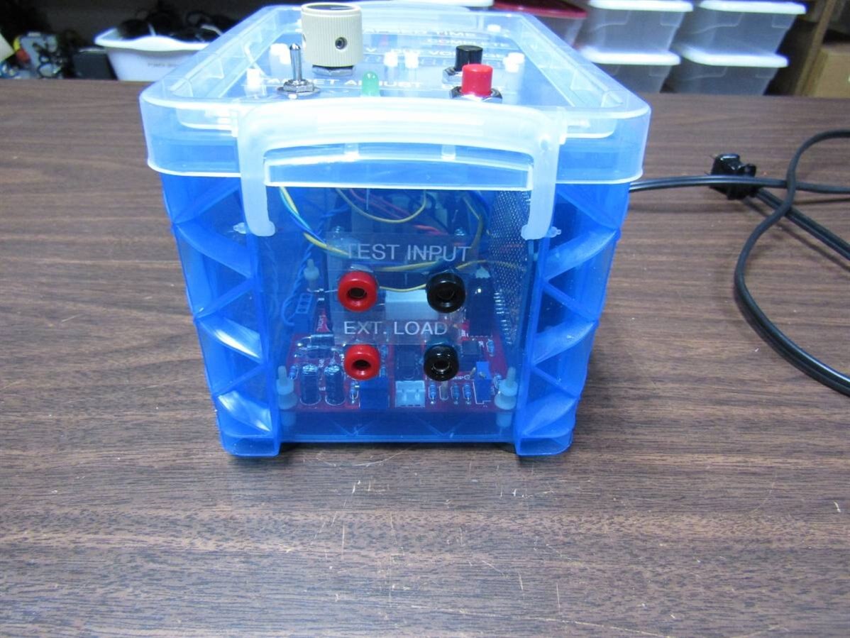
Now that I had a functional unit I decided to test it by putting a AA battery under load and seeing how long it would take for it to drop below 1 volt. The PDT has a set of banana jacks that allow an external electronic load to be attached to the device that is being tested.


image


I hooked up the external electronic load and set it to 300 mA. The Target voltage on the PDT was set at 1 volt and the AA battery was hooked to the circuit and the Start Button on the PDT was pushed. I walked away and returned several hours later. On return the complete light was on and the time on the PDT was waiting at the push of the TIME button. Sorry I have no photos or videos as I forgot in my excitement.


Now I wanted to run some experiments that were more predictable so I found the largest non-super capacitor that I had which happened to be 33,000 uF. My plan was to charge the capacitor to 30 volts and then time it through one time constant. I did not need the external electronic load this time as I would use the inherent 75K ohms input resistance of the PDT created by the voltage divider for the arduino's analog inputs. One time constant below 30 volts would be 11.3 volts. Here is a picture of the setup with the 33,000 uF capacitor.


image


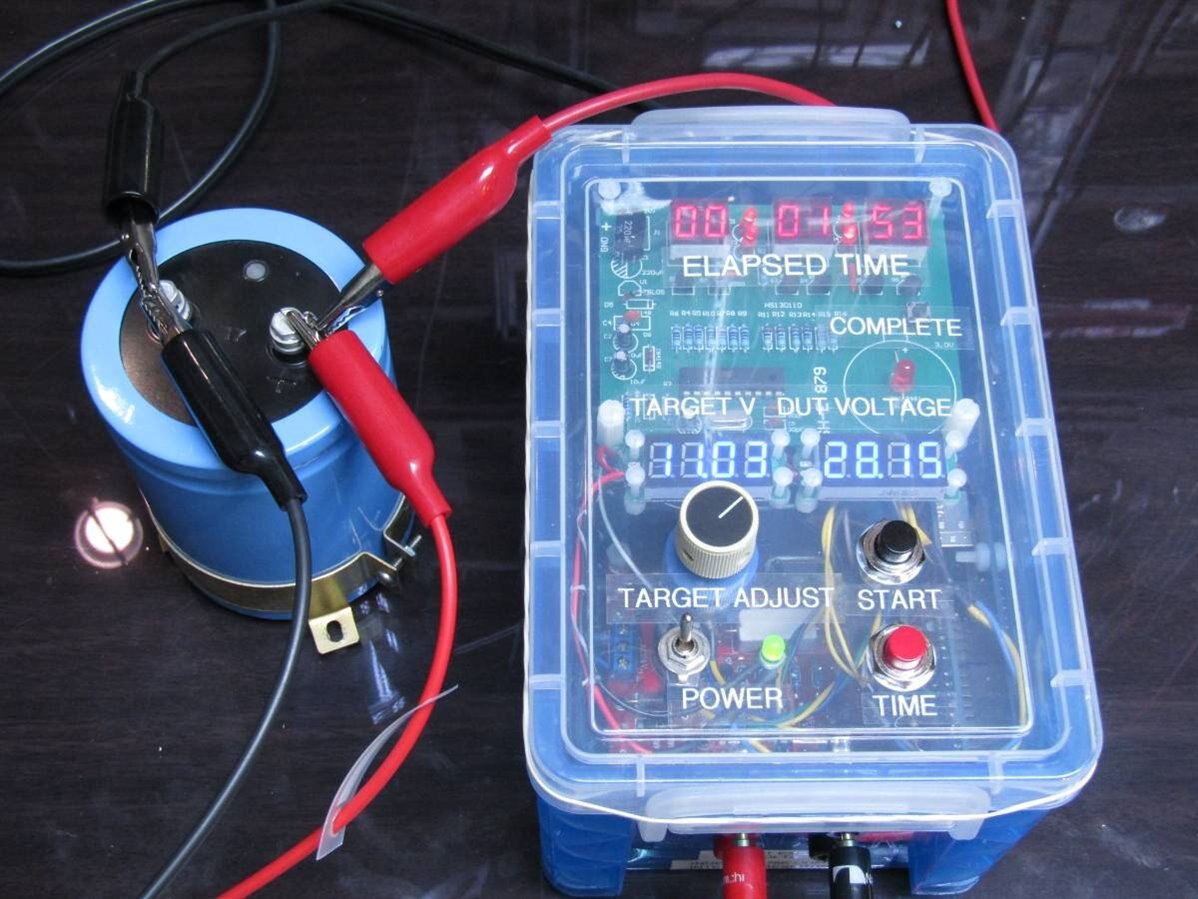
You can see that when the picture was taken 1 minute and 53 seconds had elapsed and the capacitor was down to 28.15 volts. I ran this experiment 3 times and received the following results;


Test 1 Elapsed time  41:05     Calculated capacitance assuming input resistance of 75K  =  32,900 uF

Test 2 Elapsed time  42:42     Calculated capacitance assuming input resistance of 75K  =  34,000 uF

Test 3 Elapsed time  42:00     Calculated capacitance assuming input resistance of 75K  =  33,600 uF


I wanted to produce a video to demonstrate this type of test so I chose a 350 uf capacitor and charged it to 16 volts. One time constant below 16 volts is 6.03 volts.  This should take about 30 seconds which is more appropriate for a demo video. Just for back ground on this experiment and video I had to do it 4 times before I got it this bad. What I lack as a moderator I less than make up for as a videographer but here it is:


You don't have permission to edit metadata of this video.
Edit media
x
image
Upload Preview
image


When I first felt that I needed a timer like the Process Duration Timer I was testing and comparing batteries from different manufacturers. To test batteries properly they need to be allowed to discharge at reasonable rates. The times involved made personally monitoring the process impossible. I built my first timer at that time but I have always found it clumsy to use and it lacked the range to test batteries over 12 volts. The PDT is my attempt to produce a more accurate unit with a greater range (up to 30 volts in this case). As you have seen it can also be used to time the process of capacitor discharge and with a simple interface it should be able to time any electronic or mechanical process that can be connected to a sensor or a switch. All that one has to do is sense the end of the process and pull the test voltage below the target voltage.


Thank you to my friends who have taken the time to read and make suggestions that have helped me make this a more successful project.


John


  • Sign in to reply

Top Comments

  • mcb1
    mcb1 over 8 years ago +4
    Well done For whatever reason it will not let me upload this video. https://www.youtube.com/watch?v=FPQlXNH36mI
  • jw0752
    jw0752 over 8 years ago in reply to Jan Cumps +4
    Hi Jan, The Blue Tape arrived and it makes a lot of difference: Before picture: After Picture: While I already have red tape on the red 7 segment displays I tried a second external tape on the front of…
  • mcb1
    mcb1 over 8 years ago in reply to jw0752 +3
    How do you remember I remember watching the show when I was a LOT younger and the TV offerring was 1 or 2 channels only. find these awesome clips Google is my friend. Still unsure why I couldn't embed…
  • jw0752
    jw0752 over 8 years ago in reply to mcb1

    Hi Mark,

    I have several of these kits so I will do some experimenting as you suggest. At the very least I should be able to put a scope on the transistors to see how well they are pulling the digits to Vcc.

    John

    • Cancel
    • Vote Up +2 Vote Down
    • Sign in to reply
    • More
    • Cancel
  • mcb1
    mcb1 over 8 years ago in reply to jw0752

    jw0752

    John I noted that the 470 ohm series resistors for each digit are available.

    image

    The base drive resistor is 4k7 which hopefully is turning on Q1 - Q6 fully.


    While the similar product I linked back here  https://www.element14.com/community/people/jw0752/blog/2017/07/24/process-duration-timer-blog-1-the-timer#comment-111778  uses 1k base drive and 1k series resistors.

    image


    It may be possible to do somw tweaking to get a bit more from the display.


    Mark

    • Cancel
    • Vote Up +1 Vote Down
    • Sign in to reply
    • More
    • Cancel
  • balearicdynamics
    balearicdynamics over 8 years ago

    Thank you for this project John!


    This is one if those projects from where it is most what I can learn than I can contribute. Interesting and very useful.  


    Enrico

    • Cancel
    • Vote Up +1 Vote Down
    • Sign in to reply
    • More
    • Cancel
  • jw0752
    jw0752 over 8 years ago in reply to mcb1

    Hi Mark,


    Thanks for the link to the color charts. I will try some experiments but the basic problem with the red display is that the clock is strobing the digits so each digit is only lit one sixth of the time.  I applied red filter material to the clock digits before I mounted the clock module and this helped with the contrast but it still attenuates the light output some. I may just have to make the best of it. I guess I can't complain too much based on the cost of the hardware I used.


    John

    • Cancel
    • Vote Up +1 Vote Down
    • Sign in to reply
    • More
    • Cancel
  • mcb1
    mcb1 over 8 years ago in reply to jw0752

    jw0752

    The blue colour of the box seems to be fighting you with your red display, but is aiding you with the blue one.


    I wonder if you try a green filter, whether it might help make the red standout more.

    https://www.nikonians.org/reviews/additive-and-substractive-color


    Mark

    • Cancel
    • Vote Up 0 Vote Down
    • Sign in to reply
    • More
    • Cancel
>
element14 Community

element14 is the first online community specifically for engineers. Connect with your peers and get expert answers to your questions.

  • Members
  • Learn
  • Technologies
  • Challenges & Projects
  • Products
  • Store
  • About Us
  • Feedback & Support
  • FAQs
  • Terms of Use
  • Privacy Policy
  • Legal and Copyright Notices
  • Sitemap
  • Cookies

An Avnet Company © 2025 Premier Farnell Limited. All Rights Reserved.

Premier Farnell Ltd, registered in England and Wales (no 00876412), registered office: Farnell House, Forge Lane, Leeds LS12 2NE.

ICP 备案号 10220084.

Follow element14

  • X
  • Facebook
  • linkedin
  • YouTube