element14 Community
element14 Community
    Register Log In
  • Site
  • Search
  • Log In Register
  • Community Hub
    Community Hub
    • What's New on element14
    • Feedback and Support
    • Benefits of Membership
    • Personal Blogs
    • Members Area
    • Achievement Levels
  • Learn
    Learn
    • Ask an Expert
    • eBooks
    • element14 presents
    • Learning Center
    • Tech Spotlight
    • STEM Academy
    • Webinars, Training and Events
    • Learning Groups
  • Technologies
    Technologies
    • 3D Printing
    • FPGA
    • Industrial Automation
    • Internet of Things
    • Power & Energy
    • Sensors
    • Technology Groups
  • Challenges & Projects
    Challenges & Projects
    • Design Challenges
    • element14 presents Projects
    • Project14
    • Arduino Projects
    • Raspberry Pi Projects
    • Project Groups
  • Products
    Products
    • Arduino
    • Avnet Boards Community
    • Dev Tools
    • Manufacturers
    • Multicomp Pro
    • Product Groups
    • Raspberry Pi
    • RoadTests & Reviews
  • About Us
  • Store
    Store
    • Visit Your Store
    • Choose another store...
      • Europe
      •  Austria (German)
      •  Belgium (Dutch, French)
      •  Bulgaria (Bulgarian)
      •  Czech Republic (Czech)
      •  Denmark (Danish)
      •  Estonia (Estonian)
      •  Finland (Finnish)
      •  France (French)
      •  Germany (German)
      •  Hungary (Hungarian)
      •  Ireland
      •  Israel
      •  Italy (Italian)
      •  Latvia (Latvian)
      •  
      •  Lithuania (Lithuanian)
      •  Netherlands (Dutch)
      •  Norway (Norwegian)
      •  Poland (Polish)
      •  Portugal (Portuguese)
      •  Romania (Romanian)
      •  Russia (Russian)
      •  Slovakia (Slovak)
      •  Slovenia (Slovenian)
      •  Spain (Spanish)
      •  Sweden (Swedish)
      •  Switzerland(German, French)
      •  Turkey (Turkish)
      •  United Kingdom
      • Asia Pacific
      •  Australia
      •  China
      •  Hong Kong
      •  India
      •  Korea (Korean)
      •  Malaysia
      •  New Zealand
      •  Philippines
      •  Singapore
      •  Taiwan
      •  Thailand (Thai)
      • Americas
      •  Brazil (Portuguese)
      •  Canada
      •  Mexico (Spanish)
      •  United States
      Can't find the country/region you're looking for? Visit our export site or find a local distributor.
  • Translate
  • Profile
  • Settings
Personal Blogs
  • Community Hub
  • More
Personal Blogs
John Wiltrout's Blog Putzing with a MAXIM ICL7662 Voltage Converter
  • Blog
  • Documents
  • Mentions
  • Sub-Groups
  • Tags
  • More
  • Cancel
  • New
  • Share
  • More
  • Cancel
Group Actions
  • Group RSS
  • More
  • Cancel
Engagement
  • Author Author: jw0752
  • Date Created: 3 Aug 2016 5:28 AM Date Created
  • Views 2935 views
  • Likes 5 likes
  • Comments 7 comments
  • voltage_converter
  • icl7662
Related
Recommended

Putzing with a MAXIM ICL7662 Voltage Converter

jw0752
jw0752
3 Aug 2016

Tonight I salvaged a Maxim ICL 7662 Voltage Converter from a circuit board that came out of a piece of dental equipment called a Cavitron. As I glanced over the data sheet on this little IC I was immediately captured by its simplicity of design and application. In my book the closer one can get to simplicity and still get the job done the closer one is to electronic beauty and elegance. This little circuit is beautiful and elegant. I looked the part up on Newark. Here is the listing:


http://www.newark.com/maxim-integrated-products/icl7662cpa/ic-voltage-converter-tube50/dp/58T1904


Here is a link to the Data Sheet also in case you want to  look it over for yourself. Also please note that the two illustrations posted later in this blog have been lifted from the Data Sheet.


http://pdfserv.maximintegrated.com/en/ds/ICL7662-Si7661.pdf


I began my exploration of this circuit by hooking it up as illustrated in the data sheet's typical operation:


       imageimageimage


As you can see from the diagram and the bread board we have the ICL 7662, 2 10 uF caps, and a small 100 nF decoupler that I threw in across the power inputs to the chip. The circuit is so simple it is almost trivial but it works. The +15 volts comes in and a -15 volts appears magically on pin 5 of the IC relative to ground. Oops, I don't believe in magic so here is the explanation thankfully simplified a bit by the writers of the Data Sheet.


image


The picture above is an idealized operational diagram that I moved from the Data Sheet. The ICL 7662 has an internal clock of approximately 10 kHz. This clock can be over ridden by injecting a higher frequency into pin 7 of the chip. For my exploration the internal clock was convenient so it was used. From the diagram we can see that the banks of switches ( S1, S3) and (S2, S4) are alternately closed by the clock. When (S1, S3) are closed external capacitor (10 uF in this case) is charged with the Vin. In the second half of the clock cycle (S2, S4) are closed and the charge in C1 is transferred  to external capacitor C2 (also 10 uF) which is wired such that it's positive terminal is tied to the common ground and it's negative terminal is the negative voltage output of the chip. The picture above shows the operation with the input voltage displayed on the small breadboard meter and the larger multimeter displaying the negative voltage. There is no load on the chip at this point.


For the fun of it I decided to carry this exploration one step further and hook the +/- 15 volt supplied by the ICL 7662 to an LM741 Op Amp. I decided to use a couple of 10 K resistors to center the inverting input of the 741 and a 50K potentiometer to provide a variable voltage to the non-inverting input of the 741. For an output I connected a bidirectional red / green LED to the 741 output pin. This should allow me to turn the LED from red to green by walking the voltage on the non-inverting input back and forth past the fixed voltage on the inverting input. Here is a picture of the finished circuit:


image


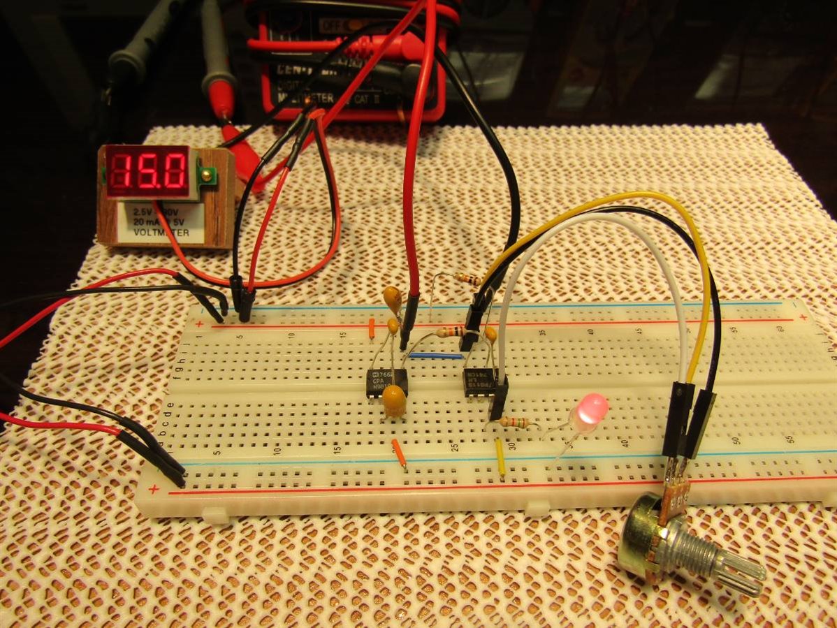
Since the picture doesn't show much here is a short video of the circuit in operation.


You don't have permission to edit metadata of this video.
Edit media
x
image
Upload Preview
image


The Maxim ICL7662 IC can be very useful in situations where one wants to power an Op Amp, Comparator, or other circuit with a +/- voltage supply and not go through all the trouble of constructing a dedicated split power supply. The output current is practically limited to about 20 mA unless your circuit can tolerate voltage drops in excess of 10%. Check the graphs in the Data sheet if you have an application to verify that these limits will work for you.


John

  • Sign in to reply

Top Comments

  • shabaz
    shabaz over 9 years ago +3
    Hi John, It is such a useful circuit, and nice method to demonstrate it, with that LED! It is so useful other manufacturers like Microchip have a version of the device too (TC7662). Although current output…
  • jw0752
    jw0752 over 9 years ago in reply to shabaz +3
    Hi Shabaz, The circuit diagram that you offered for the doubler using the AMD 660 also works just fine for the ICL7662 even though the manufacturer doesn't mention this configuration in their data sheet…
  • DAB
    DAB over 9 years ago +2
    Great post and demo John. Well done. DAB
  • shabaz
    shabaz over 9 years ago in reply to jw0752

    Hi John,


    Ahh thats interesting. Good to know!! There is often a need for a high non-standard voltage, e.g. for OLEDs, so its useful to know this is possible.

    • Cancel
    • Vote Up 0 Vote Down
    • Sign in to reply
    • More
    • Cancel
  • jw0752
    jw0752 over 9 years ago in reply to shabaz

    Hi Shabaz,

    The circuit diagram that you offered for the doubler using the AMD 660 also works just fine for the ICL7662 even though the manufacturer doesn't mention this configuration in their data sheet. Instead they have an arrangement using 2 diodes which lowers the doubling voltage by two junction drops. The ICL 7662 would be a good choice if you needed to use input voltages above 7 volts.

    John

    • Cancel
    • Vote Up +3 Vote Down
    • Sign in to reply
    • More
    • Cancel
  • jw0752
    jw0752 over 9 years ago in reply to shabaz

    Hi Shabaz,


    My AMD660s came in the other day and tonight I had time to play with them. They work very well to invert and double any input voltage up to +7 Volts. Current up to 100 mA available. Thanks for mentioning this alternative for me to check out.


    John

    • Cancel
    • Vote Up +1 Vote Down
    • Sign in to reply
    • More
    • Cancel
  • volly
    volly over 9 years ago

    jw0752. Simply excellent!

    • Cancel
    • Vote Up 0 Vote Down
    • Sign in to reply
    • More
    • Cancel
  • DAB
    DAB over 9 years ago

    Great post and demo John.


    Well done.


    DAB

    • Cancel
    • Vote Up +2 Vote Down
    • Sign in to reply
    • More
    • Cancel
>
element14 Community

element14 is the first online community specifically for engineers. Connect with your peers and get expert answers to your questions.

  • Members
  • Learn
  • Technologies
  • Challenges & Projects
  • Products
  • Store
  • About Us
  • Feedback & Support
  • FAQs
  • Terms of Use
  • Privacy Policy
  • Legal and Copyright Notices
  • Sitemap
  • Cookies

An Avnet Company © 2025 Premier Farnell Limited. All Rights Reserved.

Premier Farnell Ltd, registered in England and Wales (no 00876412), registered office: Farnell House, Forge Lane, Leeds LS12 2NE.

ICP 备案号 10220084.

Follow element14

  • X
  • Facebook
  • linkedin
  • YouTube