element14 Community
element14 Community
    Register Log In
  • Site
  • Search
  • Log In Register
  • Community Hub
    Community Hub
    • What's New on element14
    • Feedback and Support
    • Benefits of Membership
    • Personal Blogs
    • Members Area
    • Achievement Levels
  • Learn
    Learn
    • Ask an Expert
    • eBooks
    • element14 presents
    • Learning Center
    • Tech Spotlight
    • STEM Academy
    • Webinars, Training and Events
    • Learning Groups
  • Technologies
    Technologies
    • 3D Printing
    • FPGA
    • Industrial Automation
    • Internet of Things
    • Power & Energy
    • Sensors
    • Technology Groups
  • Challenges & Projects
    Challenges & Projects
    • Design Challenges
    • element14 presents Projects
    • Project14
    • Arduino Projects
    • Raspberry Pi Projects
    • Project Groups
  • Products
    Products
    • Arduino
    • Avnet Boards Community
    • Dev Tools
    • Manufacturers
    • Multicomp Pro
    • Product Groups
    • Raspberry Pi
    • RoadTests & Reviews
  • Store
    Store
    • Visit Your Store
    • Choose another store...
      • Europe
      •  Austria (German)
      •  Belgium (Dutch, French)
      •  Bulgaria (Bulgarian)
      •  Czech Republic (Czech)
      •  Denmark (Danish)
      •  Estonia (Estonian)
      •  Finland (Finnish)
      •  France (French)
      •  Germany (German)
      •  Hungary (Hungarian)
      •  Ireland
      •  Israel
      •  Italy (Italian)
      •  Latvia (Latvian)
      •  
      •  Lithuania (Lithuanian)
      •  Netherlands (Dutch)
      •  Norway (Norwegian)
      •  Poland (Polish)
      •  Portugal (Portuguese)
      •  Romania (Romanian)
      •  Russia (Russian)
      •  Slovakia (Slovak)
      •  Slovenia (Slovenian)
      •  Spain (Spanish)
      •  Sweden (Swedish)
      •  Switzerland(German, French)
      •  Turkey (Turkish)
      •  United Kingdom
      • Asia Pacific
      •  Australia
      •  China
      •  Hong Kong
      •  India
      •  Korea (Korean)
      •  Malaysia
      •  New Zealand
      •  Philippines
      •  Singapore
      •  Taiwan
      •  Thailand (Thai)
      • Americas
      •  Brazil (Portuguese)
      •  Canada
      •  Mexico (Spanish)
      •  United States
      Can't find the country/region you're looking for? Visit our export site or find a local distributor.
  • Translate
  • Profile
  • Settings
Personal Blogs
  • Community Hub
  • More
Personal Blogs
John Wiltrout's Blog Repairing a Dental X-Ray Control
  • Blog
  • Documents
  • Mentions
  • Sub-Groups
  • Tags
  • More
  • Cancel
  • New
  • Share
  • More
  • Cancel
Group Actions
  • Group RSS
  • More
  • Cancel
Engagement
  • Author Author: jw0752
  • Date Created: 24 Dec 2015 7:55 AM Date Created
  • Views 3394 views
  • Likes 4 likes
  • Comments 6 comments
  • x-ray
  • dental_x-ray_unit
  • service
Related
Recommended

Repairing a Dental X-Ray Control

jw0752
jw0752
24 Dec 2015

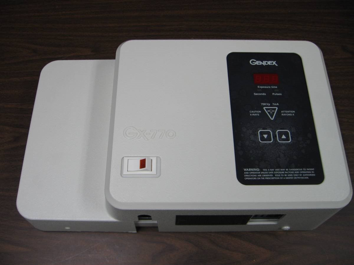
Tonight I am going to perform a simple repair on a 70 KVp 7 mA Dental X-Ray control, Model 770 made by Gendex Corp in November 1997. This x-ray unit was one of the best designed of the all the units I have worked on over the years. The fact that after 18 years it is still working and relevant to current dental x-ray techniques attests to this.


image


In the course of this repair I am going to describe the technology of the 1997 era units. Bear in mind that many improvements have taken place since then. For one thing, a lot of the dental x-rays taken today are sensed on digital sensors and actual film is no longer a common medium. This has required a change in the design of the dental x-ray units to optimized the benefits of the digital medium. This x-ray was designed with enough flexibility that it still works well with the newer digital sensors.


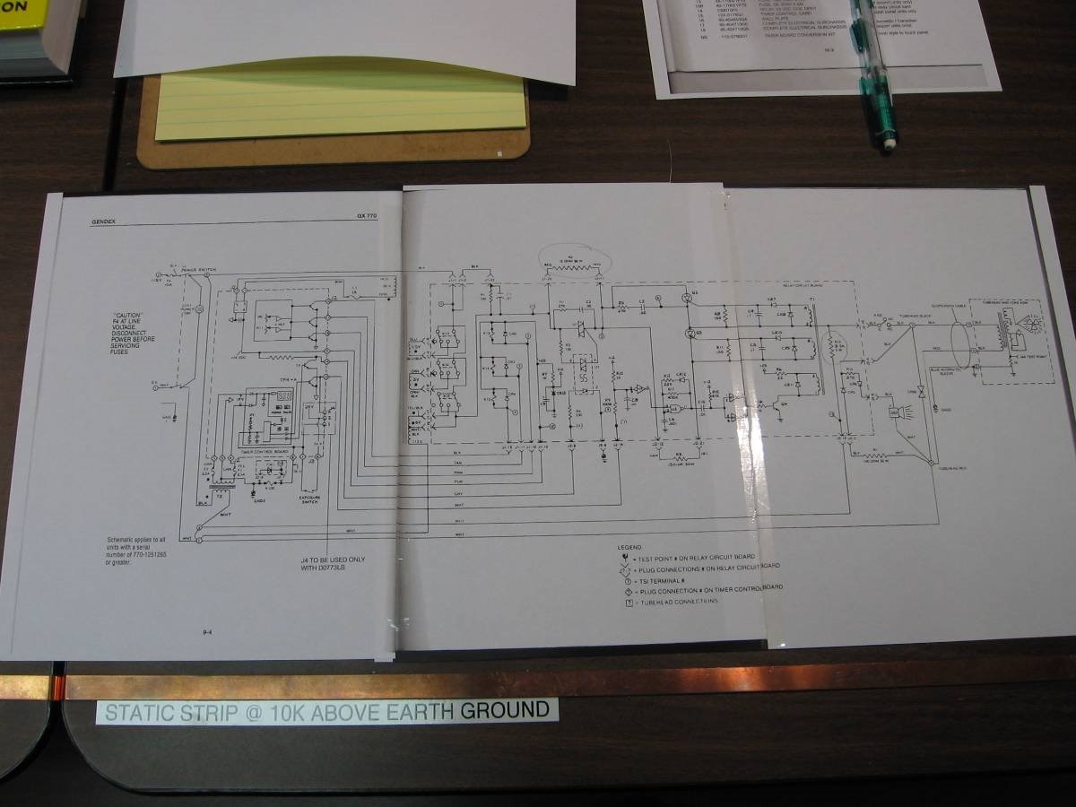
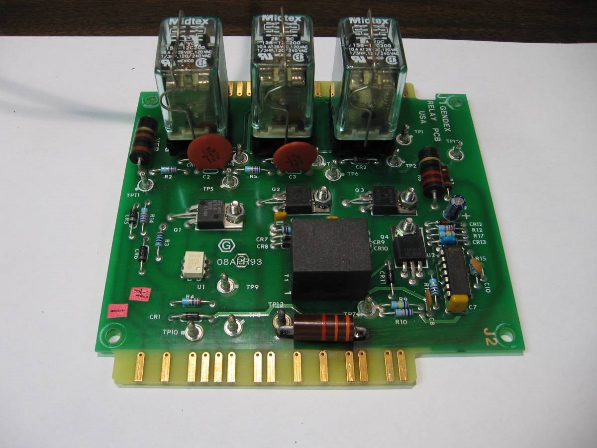
This unit failed when a wall actuation button became shorted out. This caused the unit to experience a long duration voltage to a couple of key resistors. These resistors are sized to handle the voltage that was applied but only within a duty cycle of seconds. The shorted switch caused the seconds to turn into minutes and the resistors continued heating until one of them fused and the other one carbonized. I have seen this same problem several times in the past and there is never any collateral damage except the resistors themselves. Here is a picture of the block schematic for the unit and a couple pictures of the damaged parts.


image


image


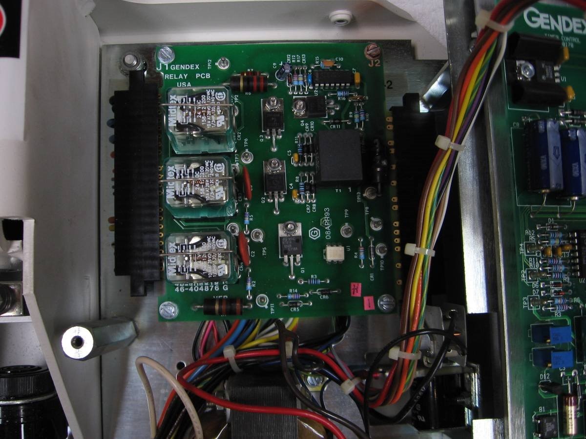
This is a poor picture, the bad resistor is along side the small black relay. A better picture of the replacement resistor is further down in the blog.


image


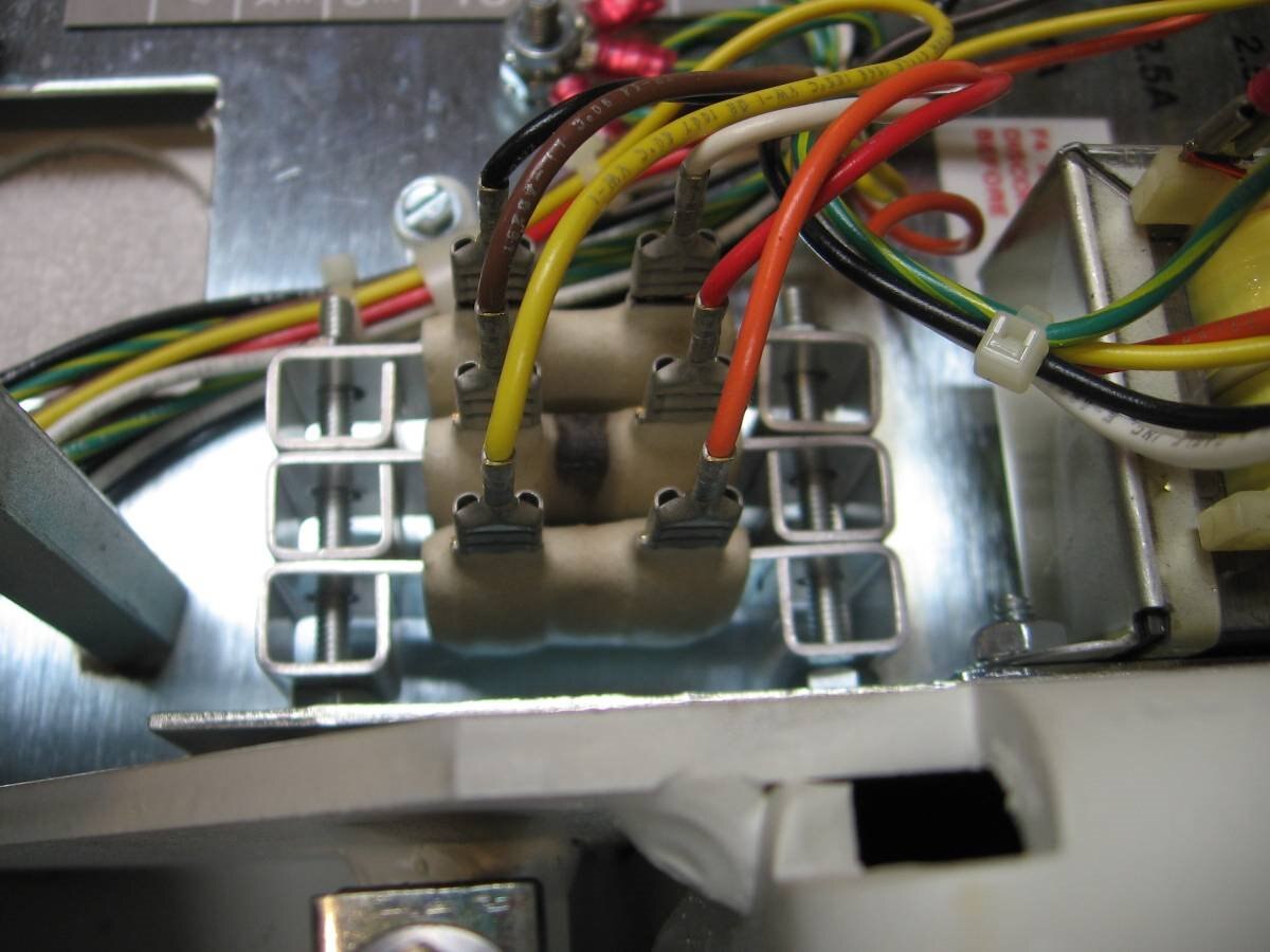
The middle 30 Watt resistor in the stack has a black band of thermal damage.


I have always been impressed with the simplicity of the design of the Gendex 770. The Head ( the part that actually produces the x-rays) contains the x-ray tube, and a transformer that produces the high voltage 70,000 volts and the voltage to heat the filament of the tube. The transformer, the tube and its support structure are immersed in special oil that serves as an insulator and a coolant for the components. Here is a picture of a dental x-ray tube.


  image


The Anode is at the bottom and the two wires at the top go to the filament that serves as the Cathode.


When the proper voltage , about 108 volts AC, is applied to the two wires to the transformer of the x-ray head the filament heats up and the 70 KVp between the anode and the cathode accelerates electrons from the heated cathode to impact on the tungsten target of the anode. When electrons of the tungsten atoms fall back to normal energy levels they give off photons of x-ray energy. The purpose of the control we are repairing today is to provide a stable AC 108 volts to the head and to provide a way to time and control the duration of the applied voltage. Surprisingly there is no attempt to rectify the voltage to the x-ray tube. Since we are applying 108 volts AC the x-ray tube is actually being subjected to 70,000 volts AC between its anode and cathode.  At its basic level the x-ray tube is a diode. It will conduct when the cathode is negative with respect to the anode and block the current when the reverse polarity is present. The result is that this dental x-ray produces a stream of 1/120 second pulses rather than a continuous beam. The control also times out a warm up period for the x-ray head. This consists of 22 pulses  or 22/60 th of a second at which time a reduced voltage is applied to the head. This allows the filament to warm but doesn't produce signifcant x-rays. After the warm up period of 22 pulses the full power of the control is applied for the number of pulses selected on the control. At the end when I test the repaired unit I have made a video and you will be able to see this warm up and full power in action. Typically the duration of the full power x-rays will be from 1 pulse to 10 pulses ( 1/60 to 1/6 second ).


Here are pictures of the replaced resistors:


image


The 2 Watt 3.3 K resistor has been replaced


image


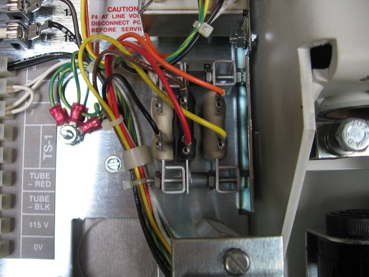
The middle resistor in this stack, a 30 W 15 Ohm, is the new replacement. This is the resistance that is put in series with the power to the x-ray head while it is in the warm up, 22 pulses, period. While the voltage applied produces more current than the resistor can handle continuous duty the 1/3 second of the warm up is too short to damage it.


Now having replaced the bad parts it is time to test the control to see if it is working properly. For my purposes I will not be testing it with an x-ray head. I will be testing it using a couple of 100 Watt light bulbs. I have connected the 100 Watt bulbs in parallel with the output that usually goes to the x-ray head. I have also jury-rigged a momentary push button to the trigger circuit of the control so I can trigger an exposure. This works well as I do not have to be concerned with ionizing radiation and I have only been asked to repair the control. Son Matt will hook up the head and test and perform calibration of the x-ray before he sells the machine. Here is what my test setup looks like:


image


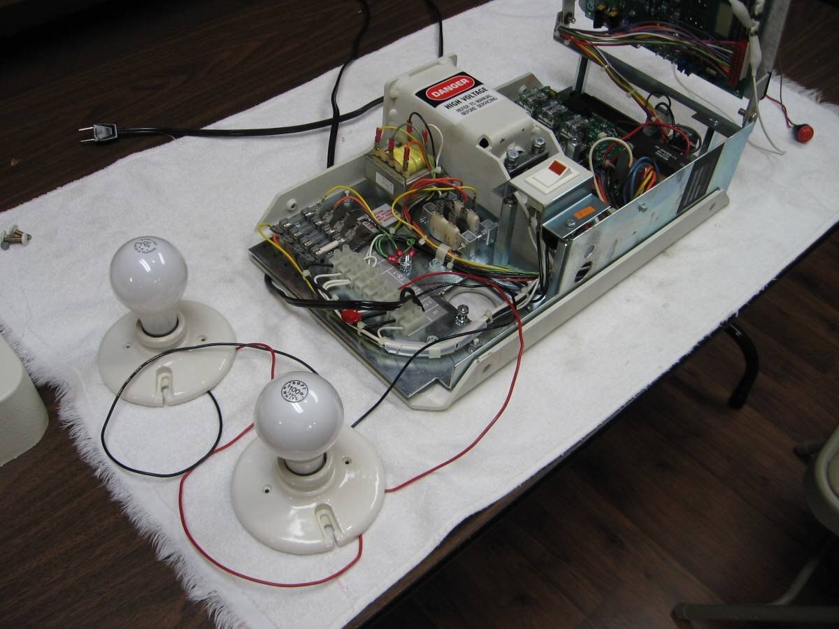
Finally here is a short video of the actual test including my not so great moderator voice. If you have questions about dental x-ray units you can post them in the comments and I will try to answer them.


You don't have permission to edit metadata of this video.
Edit media
x
image
Upload Preview
image


John

.

  • Sign in to reply

Top Comments

  • shabaz
    shabaz over 9 years ago +2
    Hi John, Great demonstration video, and detailed explanation of how such machines work. I had no idea! : ) Very interesting how it is warmed up, and how the AC frequency is used for timing that and the…
  • DAB
    DAB over 9 years ago +1
    Nice post John. I wonder if anyone got over exposed due to the faulty switch. DAB
  • jw0752
    jw0752 over 9 years ago in reply to shabaz +1
    Hi Shabaz, I hope you are having a nice Holiday. This tube was salvaged from a tube head. This is a really messy operation as all the cooling/insulating oil in the head has to be dealt with. These heads…
  • jw0752
    jw0752 over 9 years ago in reply to mcb1

    Hi Mark,

    I hope you and your family are having a great Christmas. You are correct that the first step in repairing anything is to understand what the device is suppose to do. Next one has to figure out how the specific circuit or mechanism goes about accomplishing this goal. Finally one looks for a break down in the process or the series of actions. The tough ones are in circuits that have a lot of feed back mechanisms or intermittents where the failure only happens occasionally and for no apparent reason. My favorites are where there is an apparent blast pattern to help locate the offending part.

    John

    • Cancel
    • Vote Up 0 Vote Down
    • Sign in to reply
    • More
    • Cancel
  • mcb1
    mcb1 over 9 years ago

    Nice post.

    These repairs are made to look simple, but it takes yeas of experience to understand how it should work, in order to diagnose the cause.


    Cheers

    Mark

    • Cancel
    • Vote Up +1 Vote Down
    • Sign in to reply
    • More
    • Cancel
  • jw0752
    jw0752 over 9 years ago in reply to DAB

    Hi DAB,

    Thanks for checking out my post. You ask a very good question. The failure of the circuit the way it did would have caused one firing of the tube head. Then instead of a complete shut down of the voltage to the head it was continued in the warm up mode. This is what caused the two resistors to burn out. As long as the resistors held up the head was making low level x-rays. Because of the low voltage to the head in warm up mode these x-rays would have been of lower energy, less than 50 KVp. It has been determined by the biological physicists that x-rays below the 60 KVp energy level are not useful in making good dental film images. The x-ray energies that come off a raw x-ray tube are spread in the typical bell shaped curve. Since the x-rays below 60 KVp are more harmful to the patient than they are useful the dental x-ray head has filters in place in the collimator that minimize the low energy x-ray photons. These filters are in the form of thin aluminum plates. The plates effectively absorb the low energy x-rays and therfore the low KVp intensity of the beam that leaves the x-ray head is minimal. When the head is fully power the 70 KVp x-ray photons have no problem passing through the aluminum and these photos make up the bulk of the radiation that exposes the film or sensor. The head running in warm up mode does produce low energy x-rays but because of the aluminum filters very little of this low energy radiation actually leaves the head.

    John

    • Cancel
    • Vote Up 0 Vote Down
    • Sign in to reply
    • More
    • Cancel
  • jw0752
    jw0752 over 9 years ago in reply to shabaz

    Hi Shabaz,

    I hope you are having a nice Holiday. This tube was salvaged from a tube head. This is a really messy operation as all the cooling/insulating oil in the head has to be dealt with. These heads were designed and manufactured to be used until failure and then replaced. Since they are very expensive there are actually guys who have figured out how to crack them open, replace tubes, and repair arcs and then reseal them with the proper amount of oil. It seems that it is difficult to design the dedicated repair guy out of the equation. I'm glad you like the post. Thanks for all your support this last year.

    John

    • Cancel
    • Vote Up +1 Vote Down
    • Sign in to reply
    • More
    • Cancel
  • DAB
    DAB over 9 years ago

    Nice post John.


    I wonder if anyone got over exposed due to the faulty switch.


    DAB

    • Cancel
    • Vote Up +1 Vote Down
    • Sign in to reply
    • More
    • Cancel
>
element14 Community

element14 is the first online community specifically for engineers. Connect with your peers and get expert answers to your questions.

  • Members
  • Learn
  • Technologies
  • Challenges & Projects
  • Products
  • Store
  • About Us
  • Feedback & Support
  • FAQs
  • Terms of Use
  • Privacy Policy
  • Legal and Copyright Notices
  • Sitemap
  • Cookies

An Avnet Company © 2025 Premier Farnell Limited. All Rights Reserved.

Premier Farnell Ltd, registered in England and Wales (no 00876412), registered office: Farnell House, Forge Lane, Leeds LS12 2NE.

ICP 备案号 10220084.

Follow element14

  • X
  • Facebook
  • linkedin
  • YouTube