element14 Community
element14 Community
    Register Log In
  • Site
  • Search
  • Log In Register
  • Community Hub
    Community Hub
    • What's New on element14
    • Feedback and Support
    • Benefits of Membership
    • Personal Blogs
    • Members Area
    • Achievement Levels
  • Learn
    Learn
    • Ask an Expert
    • eBooks
    • element14 presents
    • Learning Center
    • Tech Spotlight
    • STEM Academy
    • Webinars, Training and Events
    • Learning Groups
  • Technologies
    Technologies
    • 3D Printing
    • FPGA
    • Industrial Automation
    • Internet of Things
    • Power & Energy
    • Sensors
    • Technology Groups
  • Challenges & Projects
    Challenges & Projects
    • Design Challenges
    • element14 presents Projects
    • Project14
    • Arduino Projects
    • Raspberry Pi Projects
    • Project Groups
  • Products
    Products
    • Arduino
    • Avnet & Tria Boards Community
    • Dev Tools
    • Manufacturers
    • Multicomp Pro
    • Product Groups
    • Raspberry Pi
    • RoadTests & Reviews
  • About Us
  • Store
    Store
    • Visit Your Store
    • Choose another store...
      • Europe
      •  Austria (German)
      •  Belgium (Dutch, French)
      •  Bulgaria (Bulgarian)
      •  Czech Republic (Czech)
      •  Denmark (Danish)
      •  Estonia (Estonian)
      •  Finland (Finnish)
      •  France (French)
      •  Germany (German)
      •  Hungary (Hungarian)
      •  Ireland
      •  Israel
      •  Italy (Italian)
      •  Latvia (Latvian)
      •  
      •  Lithuania (Lithuanian)
      •  Netherlands (Dutch)
      •  Norway (Norwegian)
      •  Poland (Polish)
      •  Portugal (Portuguese)
      •  Romania (Romanian)
      •  Russia (Russian)
      •  Slovakia (Slovak)
      •  Slovenia (Slovenian)
      •  Spain (Spanish)
      •  Sweden (Swedish)
      •  Switzerland(German, French)
      •  Turkey (Turkish)
      •  United Kingdom
      • Asia Pacific
      •  Australia
      •  China
      •  Hong Kong
      •  India
      • Japan
      •  Korea (Korean)
      •  Malaysia
      •  New Zealand
      •  Philippines
      •  Singapore
      •  Taiwan
      •  Thailand (Thai)
      • Vietnam
      • Americas
      •  Brazil (Portuguese)
      •  Canada
      •  Mexico (Spanish)
      •  United States
      Can't find the country/region you're looking for? Visit our export site or find a local distributor.
  • Translate
  • Profile
  • Settings
Personal Blogs
  • Community Hub
  • More
Personal Blogs
John Wiltrout's Blog Zener & LED Tester
  • Blog
  • Documents
  • Mentions
  • Sub-Groups
  • Tags
  • More
  • Cancel
  • New
  • Share
  • More
  • Cancel
Group Actions
  • Group RSS
  • More
  • Cancel
Engagement
  • Author Author: jw0752
  • Date Created: 24 Apr 2017 4:13 AM Date Created
  • Views 1353 views
  • Likes 6 likes
  • Comments 6 comments
  • test_equipment
  • led_tester
  • zener_tester
Related
Recommended

Zener & LED Tester

jw0752
jw0752
24 Apr 2017

While sorting out and reorganizing my collection of mostly salvaged zeners the other day I began to imagine what I would have to do to make a simple tester. In the past I have set up the power supply, milliammeter, voltmeter, and a variety of current limiting resistors to test the questionable zeners. After considering the problem for a while I decided that a custom power supply with a few modifications would make a perfect zener tester. I also realized that it would also do double duty as an LED tester.


Here are the parameters of the modified power supply that I envisioned.


Variable voltage control from zero to thirty volts.


Variable current limit from zero to 1000 mA.


Digital display of output current in mA and voltage across the device under test.


A means to calibrate a target mA limit prior to connecting the part to be tested.


A way to connect the component to be tested easily.


A quick inventory of my parts graveyard revealed that all the necessary components for this build were already at hand. I would use the same Chinese power supply kit that I had been using in my recent bench power supply builds.


image


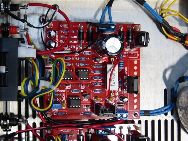
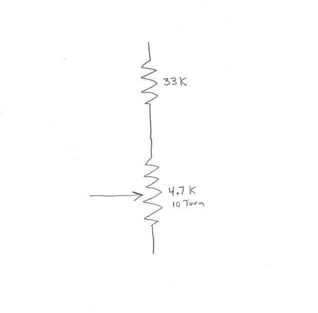
This board which is available from a Chinese Source for $10 accepts an AC input of 24 Volts and will control 0 to 30 volts output at a max 3 Amps. It also has a current limit control so that one can turn the voltage up all the way and it will self regulate the voltage to produce a constant current output. This constant current control was exactly what I needed to make the zener tester work. Since the applications that I will be testing will require currents in the low mA range I began by seeing if I could make the board work well in this range. The unit comes with a 10K potentiometer that with a 270 degree turn moves the current limit from 0 to 3 amps. For this project my preference would be a ten turn pot that controls the current between 0 and 1000 mA. After some experimentation I found that by substituting the following circuit in place of the original 10 K pot I got the result I wanted.


image


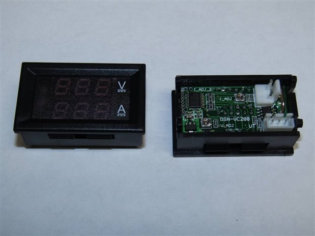
The next problem that I would have to overcome was the display of the digital meter that I hoped to use. I have used these meters on my power supply builds and they will display 0 to 100 volts to a resolution of one tenth of a volt. This will be satisfactory for my needs but the current section with a built in shunt that displays 0 to 10.0 Amps will not have the resolution that I need. I began modification of the meter by removing the factory current shunt and the installation of some low ohm resistors. After several failures I finally got close with (2) 0.1 ohm resistors in parallel. I was then able to fine tune them by adding extra solder to the leads to slightly lower their resistance further. The end result was not off as much as the linearity of the meter over the 0 to 1000 mA range so I was satisfied. The beauty of making test gear for oneself is that you can tolerate the accompanying imperfections with more grace. Here are pictures of the meter front and back.


image


I decided to put a switch on the output that would allow me to switch the control board's output between a dummy load that I could use to precalibrate the target mA and the actual output to the test leads. By having a center off for the switch I have the added benefit of a parking position between tests. This idea of the switch was given to me a couple years ago by mcb1 in one of the many inspirations he has contributed to my devices over the years.


By now I had collected the case, transformer, control board, meter, and other parts I would need.


I tested the transformer that was a perfect fit for the enclosure and I was dismayed that it put out 30 VAC instead of the 24 VAC required by the board. I have had enough experience with the board to know that this voltage level would stress and probably damage the circuit. In a normal build I would have gone in search of a different transformer but two things made me reconsider. Number one, it was a perfect physical fit which is not always the easy part. Secondly, this application had a relatively low power requirement. I decided to try an old trick where loss of overall power isn't a problem and went in search of a small transformer or inductor that I could put in series with the main transformer. Just as we can use a resistor divider to adjust voltages I would make an inductive divider to lower the voltage to the primary of the transformer. With some luck I found the secondary of a small transformer that moved the primary voltage of my main transformer to 96 VAC and the secondary voltage to a very acceptable 24.4 VAC. In the pictures that follow you can look for the small blue transformer serving as an inductive voltage drop for the main transformer. I did not check it but I was probably inducing a hundred volts or more on its primary. I cut the leads off flush and sealed them with epoxy so they would not be a factor. I have made a note for an experiment some night to see if I can adjust the voltage output of one transformer by loading the secondary of a second transformer that is in series with it.


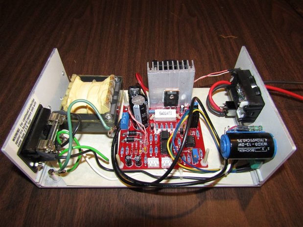
Here are some pictures of the build sequence. You may notice that I do not try to give instructions for building any of my projects. This is because my builds all come from my own pile of junk parts and most would not be able to be duplicated by a second builder. Even I am not usually able to duplicate a build. The idea of the build is however always offered to anyone interested and I will always answer questions below as to how you can integrate your own pile of parts to do something similar.


image

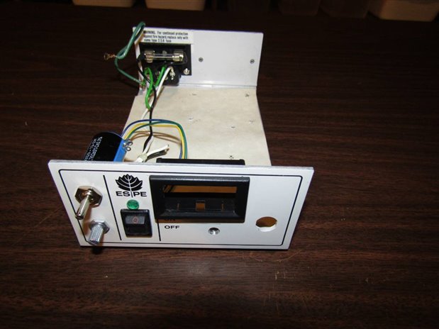
The case came from an old dental cure light. I have used these cases in the past for single channel bench power supplies.


image

Before wiring has begun


image

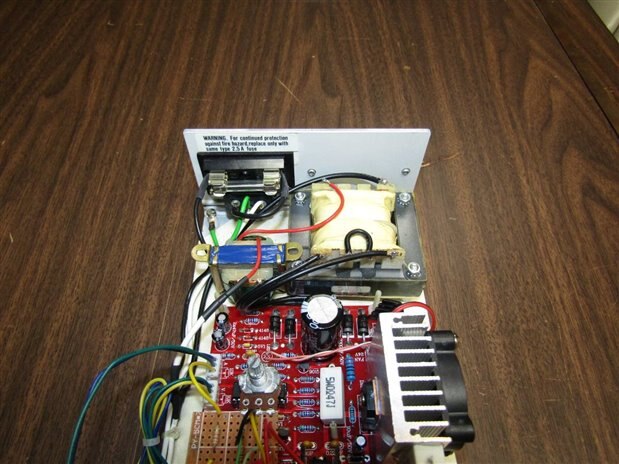
The little blue inverted transformer in the back left area is the inductor that is reducing the voltage of the main transformer primary.


image

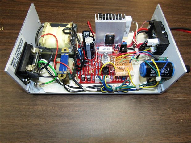
The completed wiring prior to closure of the case.


image

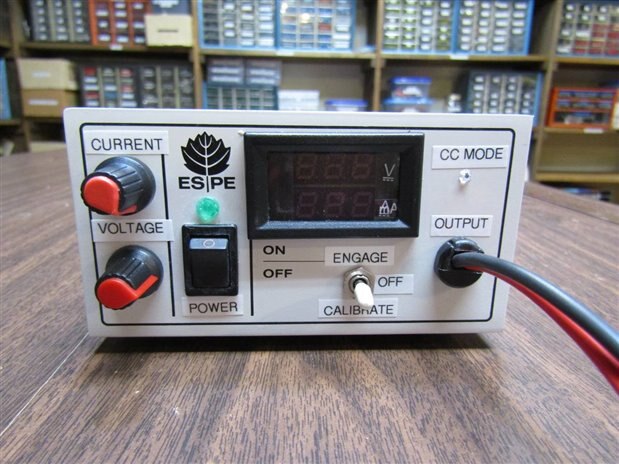
The finished front panel.


image

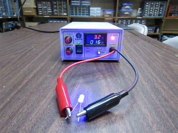
Testing a Blue LED at 16 mA and the meter showing the junction drop of 3.2V.


The bright CC Mode light comes on whenever the board is controlling the voltage to maintain the target current.


John


  • Sign in to reply

Top Comments

  • mcb1
    mcb1 over 8 years ago +2
    Well done. You've mounted the three position switch upside down I'm busy putting my supply together based on your posts, and I'm pleased to see that my initial thoughts about the meter cutout was right…
  • jw0752
    jw0752 over 8 years ago in reply to mcb1 +2
    Hi Mark, I don't want to overwhelm you with Chinese projects but check out this one. https://www.banggood.com/Orignal-JYE-Tech-DS0150-15001K-DSO-SHELL-DIY-Digital-Oscilloscope-Kit-With-Housing-p-1093865…
  • jw0752
    jw0752 over 8 years ago in reply to dougw +2
    Hi Doug, I just did a blog about this: https://www.element14.com/community/people/jw0752/blog/2017/04/25/building-the-dso-shell-15001k-oscilloscope I believe that the kit is also available where the SMD…
Parents
  • mcb1
    mcb1 over 8 years ago

    Well done.

    You've mounted the three position switch upside down image


    I'm busy putting my supply together based on your posts, and I'm pleased to see that my initial thoughts about the meter cutout was right.

    (remove the electronics, fit the bezel in the hole, and then put the electronics back.)


    The meters I brought were 0-100v at 10A,

    https://www.banggood.com/Dual-Red-Blue-LED-Digital-Voltmeter-Ammeter-Panel-Volt-Gauge-Meter-p-918687.html


    but I see this seller has a 1A version.

    https://www.banggood.com/0_28-Inch-Dual-Display-Red-Blue-LED-Panel-4_5-30V-Digital-Voltmeter-Ammeter-1-100A-p-1093413.ht…


    The kit is interesting as the 2SD1047 is capable of 140v at 12A, so the 3A limit is well down it's ability.

    The board tracks will be the limiting factor, along with the control circuitry, but it is nice to know the output transistor is probably the last to go.


    Fan control.

    For anyone interested I did an Arduino sketch that allows for multiple DS18B20 sensors.

    It takes the highest value and controls the output using that temperature.


    /*
      Temp Controlled Relay
    
     DS18B20 Temperature chips on pin 2
     4k7 pullup between pin 2 and +5v.
    
       Connections:
      DS18B20 Pinout (Left to Right, pins down, flat side toward you)
      - Left   = Ground
      - Center = Signal (Pin 2):  (with 3.3K to 4.7K resistor to +5 or 3.3 )
      - Right  = +5 or +3.3 V
    
     Pin assignments
     Pin 0  Rx
     Pin 1  Tx
     Pin 2  Temp sensor DS18B20
     Pin 7  Relay 1 output (HIGH to make it turn ON)
    
    
     Created 19 Apr 2017
     by Mark Beckett
    
     based on the code here http://forum.arduino.cc/index.php?topic=72654.msg546490#msg546490
        
     */
    
    // include the library code:
    
    #include <OneWire.h>
    #define DS18B20_PIN 2
    
    // DS18B20 Temperature chip i/o
    OneWire ds(DS18B20_PIN);                 // TempSensor
    
    // maximum sensors on the bus
    #define M 5
    
    // actual sensors detected
    byte m = 0 ;
    
    // addresses
    byte addr[M][8];
    
    //Outputs
    const int Relay1 = 7;               // Relay 1 Output
    const int LedPin = 13;              // LED on pin 13
    
    //Settings
    int Highest = 0;                     // Highest of all sensors.
    int HighTempOn = 45;                 // High Temperature On setting
    int HighTempOff = 30;                // High Temperature Off setting
    
    //-------------------------------------------------------------------------
    
    void setup_tempsense ()
    {
      m = 0 ;
      while (ds.search (addr[m]))
      {
        Serial.print ("Found address ") ;
        Serial.print (m, DEC) ;
        Serial.print (":  ") ;
        show_id (m) ;
        Serial.println () ;
        if (OneWire::crc8 (addr[m], 7) != addr[m][7])
        {
          Serial.println ("CRC is not valid!") ;
          return ;
        }
        if (addr[m][0] != 0x28)
        {
          Serial.println ("Device is not a DS18B20 family device.") ;
          return ;
        }
        m++ ;
      }
    
      Serial.println("No more addresses.") ;
      ds.reset_search () ;
    
    }
    
    void show_id (byte m)
    {
        for (byte i = 6 ; i >= 1 ; i--)
        {
          Serial.print (addr[m][i] >> 4, HEX) ;
          Serial.print (addr[m][i] & 15, HEX) ;
        }
    }
    
    // asynchrounous start conversion
    int start_conversion (byte i)
    {
      // The DallasTemperature library can do all this work for you!
    
      ds.reset () ;
      ds.select (addr[i]) ;
      ds.write (0x44) ;         // start conversion, with parasite power on at the end
    }
    
    // asynchrounous read result
    int read_conversion_result (byte i)
    {
      byte present = ds.reset () ;
      ds.select (addr[i]) ;   
      ds.write (0xBE) ;         // Read Scratchpad
    
      byte data[9];
      for (byte i = 0 ; i < 9 ; i++)           // we need 9 bytes
      {
        data[i] = ds.read();
      }
      int temp = (data [1] << 8) | data[0] ;   // just want temperature
      return temp ;
    }
    
    
    // synchronous call to read temperature from one sensor
    int read_temp (byte i)
    {
      start_conversion  ;
      delay (800) ;     // maybe 750ms is enough, maybe not
      return read_conversion_result  ;
    }
    
    
    void setup ()
    {
      Serial.begin (57600) ;
       
      //Define the pins
      pinMode(Relay1, OUTPUT);
      digitalWrite (Relay1, LOW);    //Relay is OFF 
      delay (500) ;
      
      setup_tempsense () ;
    
    }
    
    void loop ()
    {
      // start all the conversions
      for (byte i = 0 ; i < m ; i++)
      {
        start_conversion  ;
      }
      // share the wait
      delay (750) ;
      // read all the results
      for (byte i = 0 ; i < m ; i++)
      {
        Serial.print ("dev ") ;
        show_id  ;
        Serial.print (":  ") ;
        int temp = read_conversion_result  ;
        float centigrade = ((float) temp) * 0.0625 ;
        Serial.print (centigrade) ;
        Serial.println ("C") ;
    //    // maintain stats:
    //    sums [i] += centigrade ;
    //    sqsums [i] += centigrade*centigrade ;
        
        if(centigrade > Highest)
        {
          Highest = centigrade;
        }
        
      }
    
      Serial.println () ;
      RelayControl();
      Highest = 0;            //reset the reading at each trip thru the sensors.
      delay (250) ;
    }
    
    void RelayControl() 
    {
           //Relays are ON when the output pin is HIGH
    
           if (Highest >= HighTempOn)                              //reading is above or equal to the setting
           {
             digitalWrite(Relay1,HIGH);
             digitalWrite(LedPin, HIGH);
           }
           
           if (Highest <= HighTempOff)                              //reading is below or equal to the setting
           {
             digitalWrite(Relay1,LOW);
             digitalWrite(LedPin, LOW);
           }
    
    }


    Line 36 allows the maximum number of sensors to set (currently 5)

    Line 50 and 51 determine the ON and OFF temperature


    Mark

    • Cancel
    • Vote Up +2 Vote Down
    • Sign in to reply
    • More
    • Cancel
  • jw0752
    jw0752 over 8 years ago in reply to mcb1

    Hi Mark,

    I don't want to overwhelm you with Chinese projects but check out this one.


    https://www.banggood.com/Orignal-JYE-Tech-DS0150-15001K-DSO-SHELL-DIY-Digital-Oscilloscope-Kit-With-Housing-p-1093865.html?rmmds=myorder


    They are only 100K bandwidth but they even have a button you can push and it displays frequency, period, Vmax, Vmin, VPP, Vav, and Vrms. I have put 2 of them together so far and for $20. it is a fun little project and the thing really works quite well.


    You are using the same meters I am using and they do a fairly good job. I also learned to bevel the hole I cut for them if the face plate has any thickness so that the tabs can go back to their normal position. It is always a learning game but lots of fun along the way.


    John

    • Cancel
    • Vote Up +2 Vote Down
    • Sign in to reply
    • More
    • Cancel
  • dougw
    dougw over 8 years ago in reply to jw0752

    How much assembly is required on those scopes? How much is already complete in the kit?

    • Cancel
    • Vote Up 0 Vote Down
    • Sign in to reply
    • More
    • Cancel
  • jw0752
    jw0752 over 8 years ago in reply to dougw

    Hi Doug,


    I just did a blog about this:


    https://www.element14.com/community/people/jw0752/blog/2017/04/25/building-the-dso-shell-15001k-oscilloscope


    I believe that the kit is also available where the SMD must also be installed but that might be more of a challenge than one would want for a scope with such limited power.


    John

    • Cancel
    • Vote Up +2 Vote Down
    • Sign in to reply
    • More
    • Cancel
Comment
  • jw0752
    jw0752 over 8 years ago in reply to dougw

    Hi Doug,


    I just did a blog about this:


    https://www.element14.com/community/people/jw0752/blog/2017/04/25/building-the-dso-shell-15001k-oscilloscope


    I believe that the kit is also available where the SMD must also be installed but that might be more of a challenge than one would want for a scope with such limited power.


    John

    • Cancel
    • Vote Up +2 Vote Down
    • Sign in to reply
    • More
    • Cancel
Children
No Data
element14 Community

element14 is the first online community specifically for engineers. Connect with your peers and get expert answers to your questions.

  • Members
  • Learn
  • Technologies
  • Challenges & Projects
  • Products
  • Store
  • About Us
  • Feedback & Support
  • FAQs
  • Terms of Use
  • Privacy Policy
  • Legal and Copyright Notices
  • Sitemap
  • Cookies

An Avnet Company © 2026 Premier Farnell Limited. All Rights Reserved.

Premier Farnell Ltd, registered in England and Wales (no 00876412), registered office: Farnell House, Forge Lane, Leeds LS12 2NE.

ICP 备案号 10220084.

Follow element14

  • X
  • Facebook
  • linkedin
  • YouTube