

ORIGINAL POST 10/03/202
UPDATED 11/03/2020 : Filter response plot added.
UPDATED 17/03/2020: Board design notes added.
This idea has been at the back of my mind for while, but got pushed to the top of the stack by a post from amiranghi who wanted to set up an Analog Devices DDS chip. This reminded me of a half started project to use an ST32H7xx type ARM processor to generate sine waves by DDS.
For those who are unfamiliar with the idea, DDS stands for Direct Digital Synthesis and it's a way of generating sine waves (actually more generally any periodic waveform). There's a Wiki page here: https://en.wikipedia.org/wiki/Direct_digital_synthesis
You can buy nice little chips from Analog Devices and others. It's also easy to get little pcbs with a variety of the AD chips and some support circuits from Ebay and other sources of cheap Chinese boards. The AD chips are fine, but not that cheap and they only generate signals :- for a Frequency Response Analyser we want to measure signals as well.
By now you should be wondering just exactly what is an FRA - unless you already know, in which case skip this bit !
A Frequency Response Analyser is an instrument which measures the output of the device under test while the DUT is driven by a sine wave signal from the FRA.
So we might use one to measure the frequency response of a filter, if it has two measuring ports we will be able to measure the phase response as well.
Rather than me go on for ages , here's another link to a nice paper from Solatron whcih describes FRAs in a lot more detail.
Solatron still make nice FRAs but they are probably outside the typical home lab budget.
https://www.ameteksi.com/products/frequency-response-analyzers/1255b-frequency-response-analyzer
The plot here is to see how much of an FRA we can get for no more than £30 (not counting the pcb).
And that's where the STM32H7 family of micros come in - they offer 480MHz clock speed, on chip double precision floating point accelerator, dual or triple 16 bit ADCs, dual 12 bit DAC and lots of memory.
There's a very cheap one for £5.67 (one off STM32H750VBT6), OK for limited work but only has 128k of RAM and that isn't enough for everything we would like to do.
The best bet for this job is the STM32H743ZIT6U which has 1Mbyte of RAM. It's supported by a Nucleo board, NUCLEO-H743ZI2 at about £21 (all Farnell prices).
I wanted the maximum frequency range I could squeeze from the processor and from past experience (I've done this before at lower speeds) I expected the H7s to be good for a 500kHz sampling rate. I want to be able to do what I call continuous wave sweeping. Pretty much any FRA has the ability to work over a range of frequencies. Many allow you to sweep the frequency but there are two ways this can be done. Often the simplest is to step the frequency from one discrete frequency to another - this is simple to do but requires that you allow settling time between steps. The other way is to sweep the frequency smoothly with no steps between the start and stop frequencies. And just to make it a little bit harder what you really need is to be able to sweep logarithmically - I can't find a DDS chip that can do continuous wave log sweeps.
The concept is simple enough but we need some tricks to make even a fast processor do what we need at 500k samples/second.
If you can't cope with maths you can skip this bit.
The DDS relies on a register called the phase accumulator (in code this is just a variable), the pa represents the angle of the sine wave sample we are making.
Make pa a 32 bit unsigned variable in the code so pa = 2^32 is an angle of 2pi radians.
For 500k samples per second we need to calculate a new sample every 2us, if we want to generate a sine wave at 125000 Hz each cycle takes 1/125000 = 8us, so there are 4 samples in each cycle.
So if we add 1/4 of 2^32 to pa each sample time we can get the value of the sample by calculating sin((pa/2^32) *2 * pi).
The pa will conveniently wrap round to zero when it reaches 2^32 - this is all very nice and it's how the chips work.
The value added to pa each sample time is the phase increment phi and for constant frequency it's a constant and we can work it out once:
phi = (2^32 * freq)/fs
If the frequency is to sweep then phi must change, and if we want continuous wave sweeping it must change every sample time (not every sine cycle but every digital sample).
For a linear sweep it's not too bad, just add a little to the phi every sample time, what you add will be (phi end - phi start)/(sample rate * sweep time)
To put some numbers in that; for 10Hz to 100kHz with a sweep time of 1000 seconds, phi_start = 8.58993459E4, phi_end = 8.58993459E8, so the phi_adder = 1.71781512
Obviously it will need more than 32 bit resolution - but the H7 with its 64 bit floating point hardware should be OK.
Log sweeps are a bit harder:
We need to multiply the phi by a constant for the sweep at each sample time. For equivalent resolution the sweep time can be reduced, we'll use 100 seconds per decade.
phi_mult = (phi_end/phi_start)^(1/(sample_rate * sweep_time)) - for the example above that's 10000^(1/1.5E8) = 1.0000000614, once again we will need 64 bit precision
The H7 floating point engine doesn't do sines or cosines so they need to be calulated in software and even on the H7 it's much too slow to do in the sample time, so we use a look up table.
The H7 DAC has only 12 bit resolution, I satisfied myself, in a not very rigorous way, that a 14bit sine table is quite enough to drive a 12 bit DAC.
The sine table is accessed by right shifting the phase accumulator by 18.
End of maths.
Implementation on the Processor
The Nucleo board I had to hand is a very early one with the Y version of the processor which has several faults:
max clock speed is only 400MHz
max AHB bus speed is restricted to 100MHz for the ADC to work correctly
the ADC is a bit duff (complex interaction problems between ADCs)
There are many ways in which the code may be constructed - I've started with the very simplest where a timer generates an interrupt every 2us and the timer interrupt code refreshes the DAC, and does all the calculations required for each sample. This isn't the most efficient way to do things because the intererrupt call and returns are wasting a lot of time and it gets very hard to write the control sections of the code because no other interrupts may be used at all. (Which makes trying to talk to a display or UART a bit horrible.)
Eventually I shall re-cast the code to use DMA to transfer data from ADCs and to DACs - which should improve the performance but will make things a bit more complicated.
At first I just want to get the DDS part working and see how well it goes.
Now for some simple code - this isn't the complete project (if any one wants it I'll post the complete Keil project on Dropbox). Please don't cut and paste this code - it's been edited for readability for this blog and I may have introduced errors - if you want to run it just let me know and I'll give a known to work version.
//------------------------------------------------------------------------------------
// h7synth_fast.c
//------------------------------------------------------------------------------------
// Copyright 2020 MK ELECTRONICS LTD
//
// AUTH: Michael Kellett
// DATE 23/02/2020
//
// H7 Synth
//
// Target  STM32H743Zi on NUCLEO H743Zi board
//
// Tool chain  KEIL
//

  This program is free software: you can redistribute it and/or modify
  it under the terms of the GNU General Public License as published by
  the Free Software Foundation, either version 3 of the License, or
  (at your option) any later version.

  This program is distributed in the hope that it will be useful,
  but WITHOUT ANY WARRANTY; without even the implied warranty of
  MERCHANTABILITY or FITNESS FOR A PARTICULAR PURPOSE. See the
  GNU General Public License for more details.

  You should have received a copy of the GNU General Public License
  along with this program. If not, see <https://www.gnu.org/licenses/>.

#include "h7synth_project.h"
#include "h7synth_fast.h"
#include "h7synth_adc.h"
#include "stm32h7xx_hal.h"
#include <stm32h7xx_hal_dac.h>
#include <math.h>


double pi = 3.14159265359;
double twopi = 0.0;
double fs = 500000.0;
uint32_t phase_acc_1 = 0;
uint32_t phase_acc_2 = 0;
double f1 = 99000.0;
double f2 = 25000.0;
uint32_t phase_step_1 = 0;
uint32_t phase_step_2 = 0;
double half_dac = 2048.0;
double scale = 1800.0;
int16_t sin_table[16384];

double start_phase_step;
double stop_phase_step;
double step_multiplier;

double fphase_acc_1 = 0.0;
double fphase_acc_2 = 0.0;
double fphase_step_1 = 0;
double fphase_step_2 = 0;

double f2p32 = 0x100000000;


uint16_t adc_idx = 0;

void synth_init(void)
{
int a;
double astep;

twopi = (double)2.0 * pi;
astep = twopi / (double)(16384);
phase_step_1 = ((double)0xffffffff  / fs * f1);
phase_step_2 = ((double)0xffffffff  / fs * f2);
for(a = 0; a < 16384; a++)
    {
    sin_table[a] = half_dac + (sin(astep * (double)a) * scale);
    }
}

void sweep_init(double fstart, double fstop, double seconds_per_decade)
{
adc_idx = 0;
TIM2->CR1 &= 0xfffffffe;                                                                // stop timer
start_phase_step = ((double)0x100000000 / fs * fstart);
stop_phase_step = ((double)0x100000000 / fs * fstop);
step_multiplier = pow((double)10.0, (1/(fs *    seconds_per_decade)));
fphase_acc_1 = 0.0;
fphase_acc_2 = 0.0;
fphase_step_1 = start_phase_step;
fphase_step_2 = start_phase_step;
TIM2->CR1 |= 0x1;
NVIC_EnableIRQ(TIM2_IRQn);
}

void TIM2_IRQHandler(void)
{
uint16_t s1,s2;

//PIN_SET(DB0);


TIM2->SR &= 0xfffe;


DAC1->DHR12R1 = sin_table[phase_acc_1 >> 18];            // write the new sample to the DAC buffer
fphase_acc_1 += fphase_step_1;                            // increment the phase accumulator
if (fphase_acc_1 > f2p32) fphase_acc_1 -= f2p32;        // floating point accumulator won't warp round on it's own at max so we have to do it
phase_acc_1 = fphase_acc_1;                                // phase_acc_1 is the uint32_t copy of the floating point "actual" accumulator

if (fphase_step_1 < stop_phase_step)                    // if sweep is still sweeping
    {
    fphase_step_1 *= step_multiplier;                    // modify the phase step
    }
//PIN_CLR(DB0);

}
All the real action happens in TIM2_IRQHandler, this is called once every 2us by hardware, the DAC is set up so that the data transfer from the buffer to the actual DAC is triggered by TIM2.
The H7 DAC needs a reconstruction filter - which looks like this:
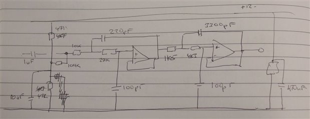
The dual amplifier is an LM7322 and the filter is a 4th order Chebyschev wit a cut off at 100kHz, designed using TI's FilterCad programme.
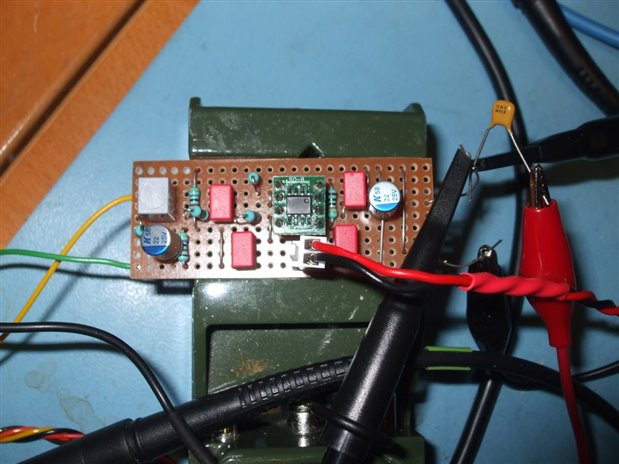
I built it on Veroboard using a little bit of the nice TI sm -> DIP converter (Farnell 3125705).
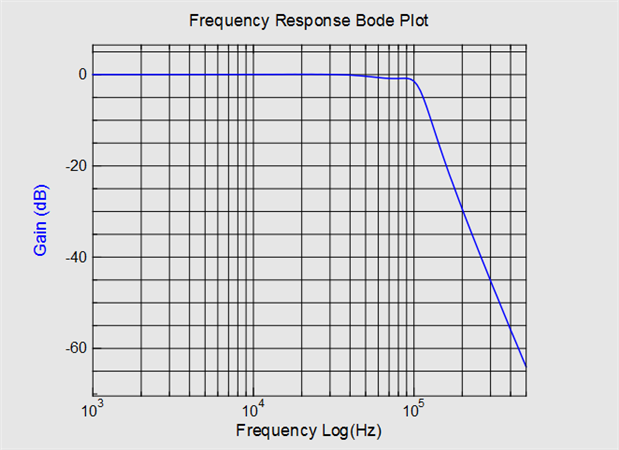
The filter works fine and the performance of the sine wave generator isn't at all bad for a 12 bit DAC.
Filter response measured by Picoscope. A bit of fine tuning could recover that 0.5dB droop but it's not at all bad for 1% standard value resistors and 5% caps.
Here a some spectra measured using a Picoscope, sine wave frequencies 2k, 25k, 37k5, 99k, 100k:
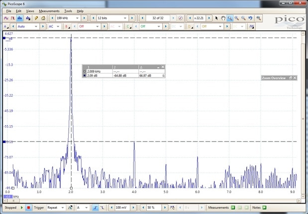

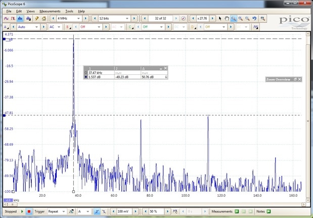

This is about as bad as the spectrum gets, harmonic distortion is low at about -60dB (0.1%) but there are some nasty spuriae close to the fundamental and only about 50dB down.

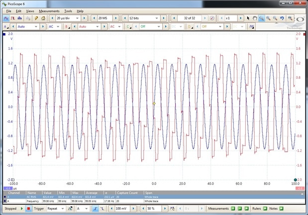
The next plot shows the output of the DAC and the output of the filter at 99kHz (in case you were wondering if we needed the filter !):
The next stage of the work is to get the ADCs working (which actually I have done) but I'm going to break off from blogging to design a pcb which can use the latest version of the processor.
MK
17/03/2020
PCB Design is complete, I'm using the 100 pin TQFP STM32H743VI processor which no one in the uK has in stock. I've ordered some from the US but with the Covid situation I'll wait until the processor actually arrive before I order the boards.
I'm going to give www.quick-teck.co.uk a go - prices nearly as keen as direct China buying but with the advantage of local currency and shipping, so no mystery about eventual price.
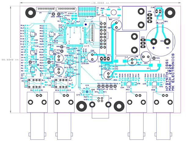
The board has the following features:
2 DC coupled input channels with relay switched 10:1 attenuator, buffer amp and 4th order anti-alias filter.
2 DC coupled output channels with 4th order anti-alias filter.
512 byte EEPROM for calibration info
Full debug connector on processor supporting serial or parallel trace (you'll need Keil Ulink PRO or ULINKplus) to get trace.
Power supply on board (almost - it doesn't have a transformer - needs about 6V AC).
Connector for Bridgetek display (SPI to intelligent display controller).
USB COM port type FTDI chip with USB connector.
120mm x 80mm
Board top side:
The schematics are in .pdf files, when I work out how to add those I will.
MK
Top Comments
-

fmilburn
-
Cancel
-
Vote Up
+4
Vote Down
-
-
Sign in to reply
-
More
-
Cancel
-

michaelkellett
in reply to fmilburn
-
Cancel
-
Vote Up
+3
Vote Down
-
-
Sign in to reply
-
More
-
Cancel
-

michaelkellett
in reply to michaelkellett
-
Cancel
-
Vote Up
+2
Vote Down
-
-
Sign in to reply
-
More
-
Cancel
Comment-

michaelkellett
in reply to michaelkellett
-
Cancel
-
Vote Up
+2
Vote Down
-
-
Sign in to reply
-
More
-
Cancel
Children