

Soldering tiny pull-up resistors to a TSSOP package.
Spurred on by Jan Cumps recent (and on-going) review of the Weller Micro Soldering Kit I decided to buy some de-soldering tweezers.
I used to have an Ersa soldering station with tweezers but they made that line obsolete many years ago and I usually use two soldering irons, one in each hand, rather than tweezers.
It's a reasonable approach for some things but not perfect.
I went for what felt like a mid price system (might be more low price), YIHUA 982D-1 PRO at about £250 for iron and tweezers. It uses the common C120 and C245 tips.
I bought mine from Amazon - you may get it a little cheaper from Aliexpress.
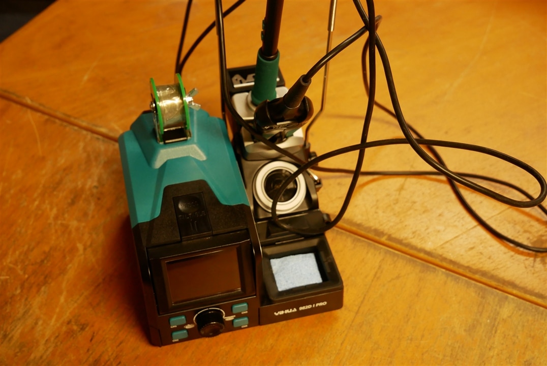
This isn't a review of the YIHUA - suffice to say that it works fine, seems to be reasonably well made, has a nice clear display - and uses widely available tips.
It looks like this:
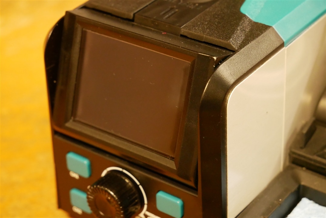
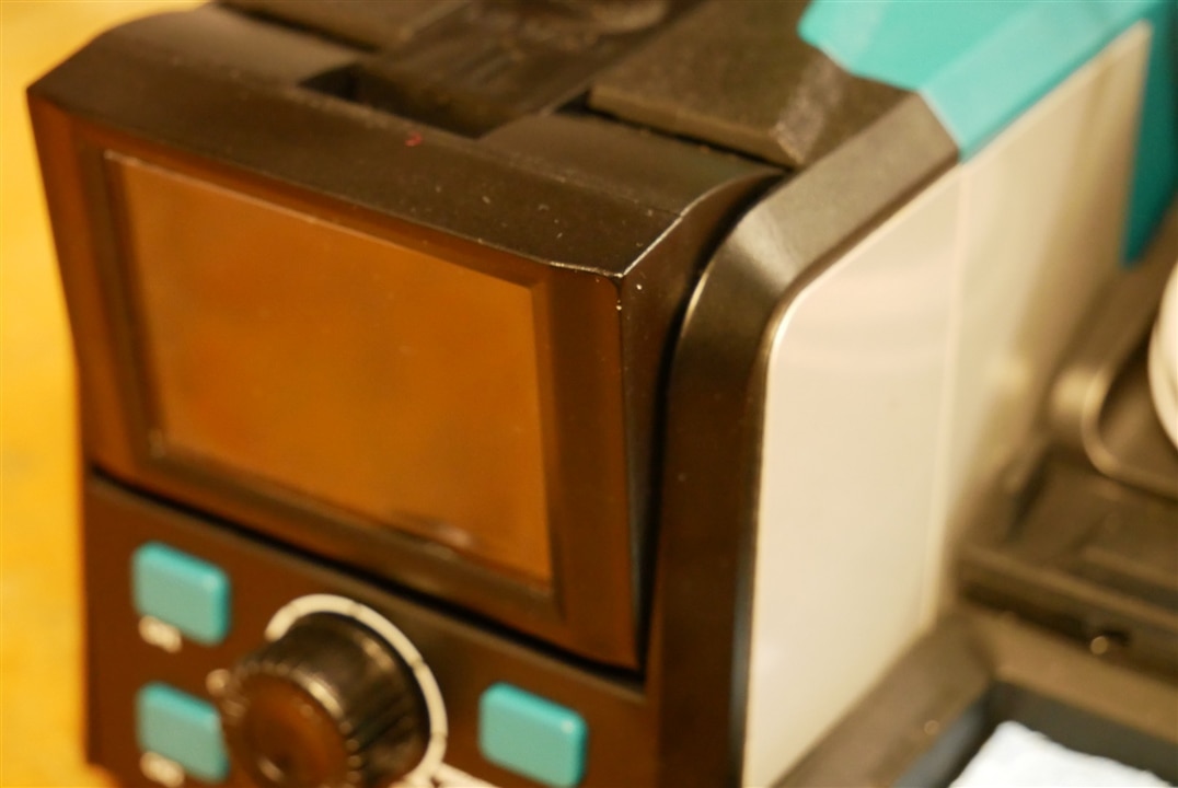
And has a weird tilting screen feature:
So - enough background - now for the problem.
I'm working on bringing up a board which is part of a set of three which make up a quite complicated power supply with super capacitor backup. I hit a snag where, because I had used the LSF02024 level shifter before, I thought I knew how it worked. It turns out that I didn't - it IS bi-directional but is not symmetrical - one side is push pull drive but the other is open drain. I used it the wrong way round and was confronted by the need to bodge in 4 pull up resistors in a hurry and with not very good access to the relevant tracks on the board.
I decided the easiest way to do would be to use a tiny resistor array that would line up with the pins on the LSF0204 and could be soldered directly to them.
Farnell sell a suitable part:

But I didn't want to waste Sunday and Monday waiting for them to arrive. My son suggested scavenging from some old gear. Obviously only quite new old gear contains suitable parts - the first few old video boards drew a blank but I found some 2 way 1k arrays in an HP computer.
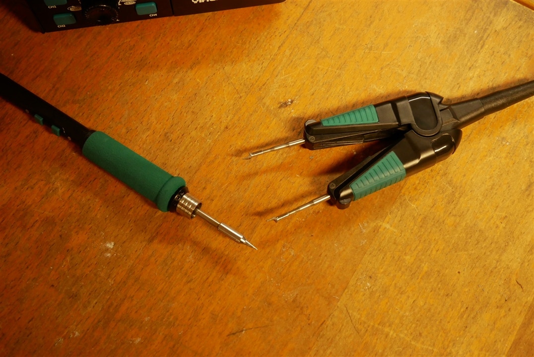
The new de-soldering tweezers did there first real work and removed two resistor arrays - there were no problems but I can't use the camera microscope to take pictures and tweeze at the same time - I tried but need more practice.
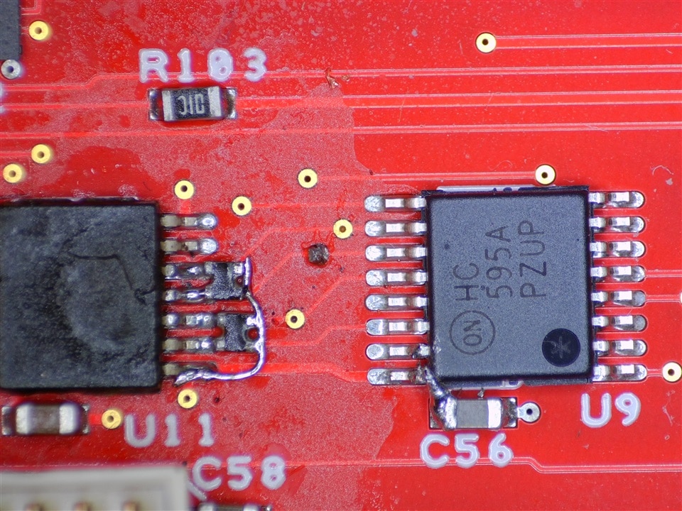
Once the arrays were out I used a spiky tip on the new iron to solder the arrays and a tiny bit of connecting wire to the chip. The trusty Wartons Future 315 flux came into play. You can see the mess it leaves in the picture. The C245 type soldering bit does a good job getting a fair bit of heat through the tiny spiky point.
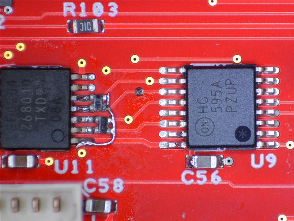
The second picture shows the board after two rinses with isopropyl alcohol. Using Safewash in the ultrasonic cleaner does a much better job but takes much longer - this will do for now. I've also cleaned up some mess I made on the adjacent chip when adding some debugging wires.
So there it is - how to add un-expected pull up resistors. (And a reminder, if one is needed, that you should never throw stuff away - even a dead computer can be a source of useful parts !)
MK

