element14 Community
element14 Community
    Register Log In
  • Site
  • Search
  • Log In Register
  • Community Hub
    Community Hub
    • What's New on element14
    • Feedback and Support
    • Benefits of Membership
    • Personal Blogs
    • Members Area
    • Achievement Levels
  • Learn
    Learn
    • Ask an Expert
    • eBooks
    • element14 presents
    • Learning Center
    • Tech Spotlight
    • STEM Academy
    • Webinars, Training and Events
    • Learning Groups
  • Technologies
    Technologies
    • 3D Printing
    • FPGA
    • Industrial Automation
    • Internet of Things
    • Power & Energy
    • Sensors
    • Technology Groups
  • Challenges & Projects
    Challenges & Projects
    • Design Challenges
    • element14 presents Projects
    • Project14
    • Arduino Projects
    • Raspberry Pi Projects
    • Project Groups
  • Products
    Products
    • Arduino
    • Avnet & Tria Boards Community
    • Dev Tools
    • Manufacturers
    • Multicomp Pro
    • Product Groups
    • Raspberry Pi
    • RoadTests & Reviews
  • About Us
  • Store
    Store
    • Visit Your Store
    • Choose another store...
      • Europe
      •  Austria (German)
      •  Belgium (Dutch, French)
      •  Bulgaria (Bulgarian)
      •  Czech Republic (Czech)
      •  Denmark (Danish)
      •  Estonia (Estonian)
      •  Finland (Finnish)
      •  France (French)
      •  Germany (German)
      •  Hungary (Hungarian)
      •  Ireland
      •  Israel
      •  Italy (Italian)
      •  Latvia (Latvian)
      •  
      •  Lithuania (Lithuanian)
      •  Netherlands (Dutch)
      •  Norway (Norwegian)
      •  Poland (Polish)
      •  Portugal (Portuguese)
      •  Romania (Romanian)
      •  Russia (Russian)
      •  Slovakia (Slovak)
      •  Slovenia (Slovenian)
      •  Spain (Spanish)
      •  Sweden (Swedish)
      •  Switzerland(German, French)
      •  Turkey (Turkish)
      •  United Kingdom
      • Asia Pacific
      •  Australia
      •  China
      •  Hong Kong
      •  India
      • Japan
      •  Korea (Korean)
      •  Malaysia
      •  New Zealand
      •  Philippines
      •  Singapore
      •  Taiwan
      •  Thailand (Thai)
      • Vietnam
      • Americas
      •  Brazil (Portuguese)
      •  Canada
      •  Mexico (Spanish)
      •  United States
      Can't find the country/region you're looking for? Visit our export site or find a local distributor.
  • Translate
  • Profile
  • Settings
Personal Blogs
  • Community Hub
  • More
Personal Blogs
NexGen Flight Simuator NexGen: Fuel Indicator: Testing The Display
  • Blog
  • Documents
  • Mentions
  • Sub-Groups
  • Tags
  • More
  • Cancel
  • New
  • Share
  • More
  • Cancel
Group Actions
  • Group RSS
  • More
  • Cancel
Engagement
  • Author Author: phoenixcomm
  • Date Created: 4 Nov 2020 7:49 PM Date Created
  • Views 3625 views
  • Likes 6 likes
  • Comments 19 comments
  • flight simulator
  • nexgen
  • arduino mega 2560
  • hdsp-213x
  • can bus
  • diy aircraft cockpit
  • recycleretrofitch
  • canaerospace
  • c progrmming
  • diy electronics
  • i2c expander
Related
Recommended

NexGen: Fuel Indicator: Testing The Display

phoenixcomm
phoenixcomm
4 Nov 2020

image
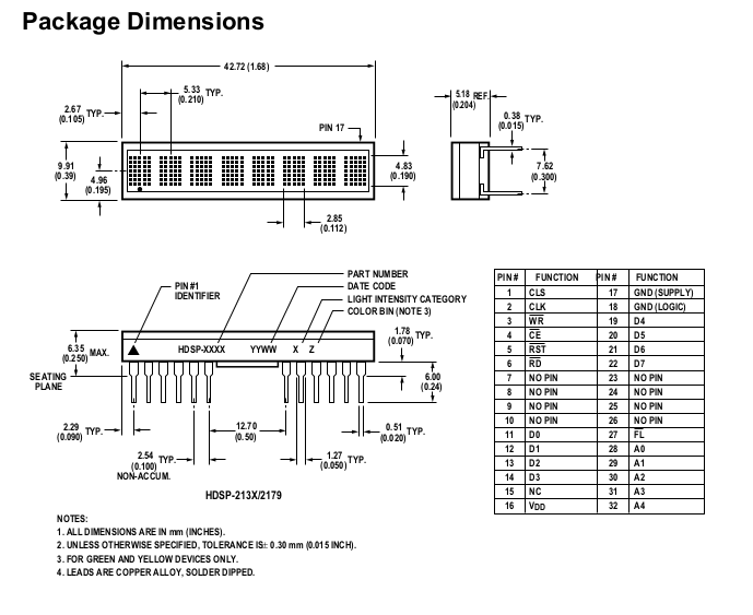
This picture on the left is just to remind you all of what I am trying to get working.  Each HDSP-2131 display has 24 pins that give you 48 pins to deal with. Now let us complicate the issue the pins come out on a 30-pin connector of which 4 are for power and ground. So now I have 28 pins for the interface.image

Other people have used similar displays ie  Wise Time with Arduino and others. Most implementations I have seen use a Flip-Flop to load the characters, but why go to that solution? The Arduino Mega 256  has only 54 digital GPIO pins. My pin count is higher as  I needed 20 pins +  8 Data  = 28 pins + 5 pins for my switches (reduced to 3-bit BCD and one interrupt pin), CAN module on pins 53, 52, 51, 50,  and the USB driver and interrupts.  This makes my head hurt! image

So I freed up my 8-bit Data-Ports pins by using an 8-bit I2C port expander which is mounted on the same  PCB that holds the 30-pin header that the display plugs into.


image

My biggest problem is that the CAN libraries (Arduino) are Master-Slave.
But CANbus is democratic which means any node can become the Master.
  And this is where the problem lies.

I still don't have a clue where to mount my Arduino Mega. image  My CAN bus modules output will be routed to a USB-A  or an RJ45F connector.

So to speed up testing before  I use my jumpers.  The only pins I will be Wire-Wrap will be the Data Port to the display header.

  • Sign in to reply

Top Comments

  • Jan Cumps
    Jan Cumps over 5 years ago +1
    It's a lot of hardware and a lot of pins to deal with. Is your goal to stick with the original technology? I see you lower the count by using the expander. Maybe we can work together here to create a design…
  • phoenixcomm
    phoenixcomm over 5 years ago in reply to DAB +1
    DAB Nope I pan on using CANaerospace which is built on top of CAN specification itself, which is also "democratic". So there is more work than I can do in 10 days. ~~ Cris
  • michaelkellett
    michaelkellett over 5 years ago in reply to michaelkellett +1
    Actually you don't need that many pins, I think you can common all the pins on the display chips except /CE, so for two displays you need only 15 pins on the processor. An ATmega168 in a 28 pin DIL package…
  • michaelkellett
    michaelkellett over 5 years ago in reply to phoenixcomm

    Well, I'm not sure what you want to do with this but you could easily (ish) replace the old controller board with you own, it would interface to the display board the same way as the old one. It might be nicer to make the old controller board work again but that doesn't seem to be an option.


    MK

    • Cancel
    • Vote Up 0 Vote Down
    • Sign in to reply
    • More
    • Cancel
  • phoenixcomm
    phoenixcomm over 5 years ago in reply to michaelkellett

    michaelkellett Take a look at this: NexGen: Hacking the Fuel Load Indicator. This shows more pics. There is nothing worth mentioning on the reverse of the display board.  just some caps, and the connector to the secondary board which held an MC68HC11 8 Bit Microprocessor but if you try and read it. It self destructs. image

    • Cancel
    • Vote Up 0 Vote Down
    • Sign in to reply
    • More
    • Cancel
  • michaelkellett
    michaelkellett over 5 years ago in reply to phoenixcomm

    I missed the address pins, still the basic idea holds, the suggestion was not that you remove the display chips from their boards but make a board that would plug into the exisitng display board. But the only picture I have to work on is the one with you holding the board in your hand.


    MK

    • Cancel
    • Vote Up +1 Vote Down
    • Sign in to reply
    • More
    • Cancel
  • phoenixcomm
    phoenixcomm over 5 years ago in reply to michaelkellett

    michaelkellett I think your pin math is way off you say I only need 15 pins ouch! Data = 8pins,  Address = 5 pins, Control = 7 pins so that's 20 pins!  I don't want to make a new PCB for the display. You should understand part of my mantra: please read NexGen: Audio Panels Ins and Outs I am using the original display PCB. If I try and remove the display and screw it up, I'm out $150.00, so removing and rebuilding the display PCB is a non-starter. 

    • Cancel
    • Vote Up 0 Vote Down
    • Sign in to reply
    • More
    • Cancel
  • phoenixcomm
    phoenixcomm over 5 years ago in reply to michaelkellett

    michaelkellett  The above solution is sort of what I have, from the factory,  Adress and Data lines, as well as the Write line, is shared be between both the Upper and Lower Display, which is 14pins,  what you end up with is 6 lines per display that are not shared so that's  12pins. So I need  26 pins.

    • Cancel
    • Vote Up 0 Vote Down
    • Sign in to reply
    • More
    • Cancel
<>
element14 Community

element14 is the first online community specifically for engineers. Connect with your peers and get expert answers to your questions.

  • Members
  • Learn
  • Technologies
  • Challenges & Projects
  • Products
  • Store
  • About Us
  • Feedback & Support
  • FAQs
  • Terms of Use
  • Privacy Policy
  • Legal and Copyright Notices
  • Sitemap
  • Cookies

An Avnet Company © 2026 Premier Farnell Limited. All Rights Reserved.

Premier Farnell Ltd, registered in England and Wales (no 00876412), registered office: Farnell House, Forge Lane, Leeds LS12 2NE.

ICP 备案号 10220084.

Follow element14

  • X
  • Facebook
  • linkedin
  • YouTube