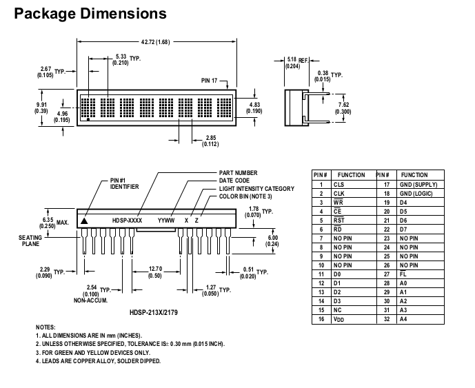
 This picture on the left is just to remind you all of what I am trying to get working. Each HDSP-2131 display has 24 pins that give you 48 pins to deal with. Now let us complicate the issue the pins come out on a 30-pin connector of which 4 are for power and ground. So now I have 28 pins for the interface.
Other people have used similar displays ie Wise Time with Arduino and others. Most implementations I have seen use a Flip-Flop to load the characters, but why go to that solution? The Arduino Mega 256 has only 54 digital GPIO pins. My pin count is higher as I needed 20 pins + 8 Data = 28 pins + 5 pins for my switches (reduced to 3-bit BCD and one interrupt pin), CAN module on pins 53, 52, 51, 50, and the USB driver and interrupts. This makes my head hurt! 
So I freed up my 8-bit Data-Ports pins by using an 8-bit I2C port expander which is mounted on the same PCB that holds the 30-pin header that the display plugs into.

But CANbus is democratic which means any node can become the Master.
And this is where the problem lies.
I still don't have a clue where to mount my Arduino Mega.  My CAN bus modules output will be routed to a USB-A or an RJ45F connector.
So to speed up testing before I use my jumpers. The only pins I will be Wire-Wrap will be the Data Port to the display header.

Top Comments