


 Flash, Food For Thought:
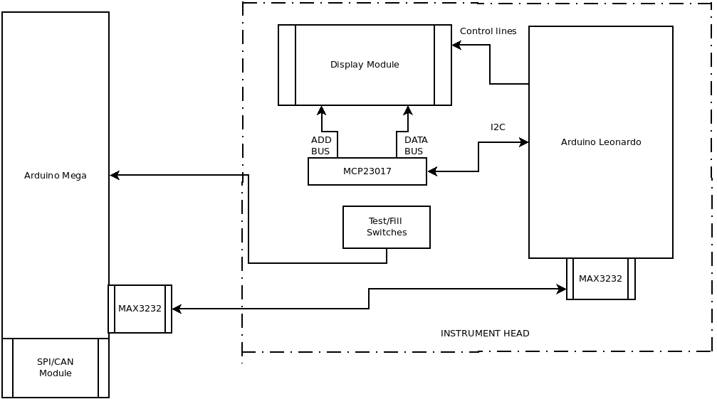
Ok, I have a Smart Display, driven by an MCP23017 16-bit I2C which requires a lot of glue, (quick count) 8 data lines, 5 address lines, and 8 control lines. If you count this on your fingers 8+5=13+8=21. Ouch. Oh yes and the 5 wires for the switches. Remember that there is about 6 feet between the Display in the panel and the Arduino Mega, and I2C has a max length of about 12 inches, or about 5 feet short!
Now, what would happen If I could remote the MCP23017?? Then the only thing left would be the Switches and the Control lines.
The Solution:
I think I am going to use two (2) CPUs
- An Arduino Leonardo will run just the display
- An Arduino Mega will run, the switch interrupts, and CANaerospace Interface.
I can use RS-232 communication between the CPUs via a TI MAX3232 RS232 to TTL Module complete with a DB-9F connector on the module. I will have to write a simple protocol, that is what the message format is. In other words, I have to create the description and the field in the message. I have done this before so rinse and repeat.
My switch debounce circuits are all pulled up by a resistor with the rest of the debounce circuitry on the remote side.
Maxim has come to the rescue with a family CMOS Switch Debouncer they come in Single/Dual/Octal packages MAX6817 which has two devices in a SOT23-6 package, but even from Newark, there is almost $6.00 each. I guess I will go back to the Schmitt trigger, SN74LS14N HEX Schmitt trigger, and an R/C network. This solution costs about 86 cents for the IC + a few resistors and a cap. Since I intend to use 5 interrupts, I will keep them on the Mega. Below is a diagram of the system.
| Wiring Plan | |||||||
|---|---|---|---|---|---|---|---|
| Arduino Mega | IO Modules | Arduino Leonardo | Instrument Head | ||||
| mnemonic | pin | mnemonic | pin | mnemonic | pin | mnemonic | pin |
| SLC | 2 | SLC | |||||
| SDA | 3 | SDA | |||||
| INT | INT | ||||||
| DP | 13 | RST1 | |||||
| DP | 12 | RST2 | |||||
| DP | 11 | CE1 | |||||
| DP | 10 | CE2 | |||||
| DP | 9 | CLK1 | |||||
| DP | 8 | CLK2 | |||||
| DP | 7 | RD1 | |||||
| DP | 6 | RD2 | |||||
| INT2 | 18 | wire one-to-one | FILL | ||||
| INT3 | 19 | wire one-to-one | TEST | ||||
| INT4 | 20 | wire one-to-one | UP | ||||
| INT5 | 21 | wire one-to-one | DOWN | ||||
| VCC | VCC | VCC | |||||
| GND | GND | GND | |||||
| RS232 | |||||||
| TX1 | 18 | RX | 0 | ||||
| RX1 | 19 | TX | 1 | ||||
| VCC | VCC | ||||||
| GND | GND | ||||||
| RS232 | |||||||
| TX | TX | ||||||
| RX | RX | ||||||
| VCC | VCC | ||||||
| GND | GND | ||||||
| CAN Module | |||||||
| CAN-SDA | 20 | SDA | |||||
| CAN-SCL | 21 | SCL | |||||
| INT3 | INT | ||||||
| VCC | VCC | ||||||
| GND | GND | ||||||
Notes:
- I will be adding and or changing pin numbers as I go along.
- 12/23/22 - Added the following: In other words, I have to create the field's descriptions and length in the message.
- 12/30/22 - Major Change. Stupid Error: CAN Module uses SPI, not I2C please see: Revised Plan of attack-UPDATE


