 The Processor Select Panel, 7-F511F00121-1 (NSN: 1290-01-438-6575), is from an Apache Longbow AH-64D.
I only need 2 inputs and two outputs, as identified in the blog post "NexGen: Component Documentation: Panel, Processor Select". Just so we don't need page flipping here they are:
- Output: SWITCH, PROCESSOR - 1, SEL1, pin 6
- Output: SWITCH, PROCESSOR - 2, SEL2, Pin 7
- input: DISPLAY, ACTIVE PROCESSOR - 1, DAP1, pin *
- input: DISPLAY, ACTIVE PROCESSOR - 2, DAP2, pin * *pins are currently unknown.
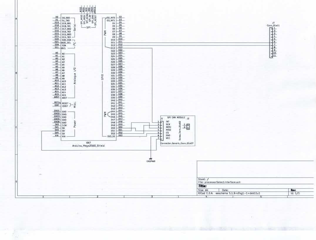
pins 2 and 3 will go to an Arduino Mega interrupt pins 12 and 13 respectively.
Communications will be via SPI to CAN module.
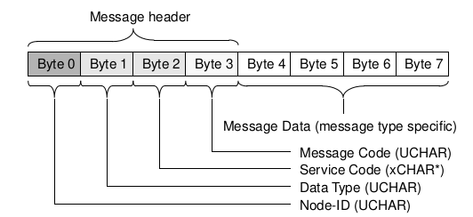
meanwhile, CANaerospace will be doing the heavy lifting. where I will use an address from the reserved space 1300-1299

| Service Responses | |||||
|---|---|---|---|---|---|
| BYTE | Data Type | VALUES | CHAN | NOD | IDS |
| BYTE 0 | Node-ID (UCHAR)1 | 1300 0x514 |
1300 0x514 |
||
| BYTE 1 | Data Type (UCHAR)2 | ||||
| BYTE 2 | Service Code (*CHAR*)3 | 0 | |||
| BYTE 3 | Message Code (UCHAR)4 | ||||
| BYTE 4 | Message Data | STATUS | 1001 | ||
| BYTE 5 | Message Data | SEL1 & SEL2 | |||
| BYTE 6 | Message Data | DAP1 | 0001 | ||
| BYTE 7 | Message Data | DAP2 | 0001 | ||
| BYTE5 DECODE 0xx0 bits 1 and 4 are pulled down = Auto Select Active 0xx1 = SEL1 Active 1xx0 = SEL2 Active |
|||||
|
|||||
The SPI/CAN module also will be using an interrupt on the Arduino pin 14. This notifies the Arduino that there is something waiting on the buffer, it could be a normal message or the Heartbeat. Below is a preliminary schematic.

