


Redacted April 10, 2024
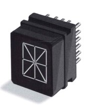
 Statement: Driving Pinlight Lamps is very challenging. The design requirements are 4vdc @ 15ma per segment, if you are interested look here.
So for the 7-segment displays, the total current is 7 x 15ma. or 105 ma. Now multiply that by 19 displays x 150ma or 1995 ma or just under 2 amps. For the 16-segment displays, of which there are 4 the total current is 16 x 4 x 15ma or 960 ma or just under 1 amp. An Arduino can't even handle one segment. So I need to buffer the displays from the Arduino.
The Plan: By the use of complementary BJT that is to say with a PNP Collector connected to the Power Rail and an NPN Emitter connected to the ground. By using the BJTs I can switch columns from the NPNs Base and each lamp segment from the PNPs Base. I don't think I will need a limiting resistor between the Power Rail and the NPNs Collector.
Power Rail |
 |
Ground Rail 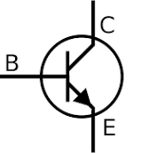 |
Most likely I will be using 2 BCD to 7-segment encoder as problems with fan out might occur. The 4 16-segment lamps will be driven directly from one 16-bit port. So using a quick math of total-segments == (16x4) + (7x19) == 64 + 133 = 197 segments! At .2 seconds per segment = 39.4 seconds to access all 197 segments. Uyk! If I ran the multiplexer twice that speed or rather half the total time per segment = 17.2 seconds. Better but still cruddy. So what would happen If I divided the tasks?
Possible Solution 1: Use four separate 74LS247 BCD to 7-Segment Decoders, each one called port A, port B, port C, port D and one Port E (16-bits). By using 3 x BCD to 1 of 8 decoders 74LS138 ganged together without using other gates.
Possible Solution 2: The mega has 50-odd digital ports? so 50/3 = 17 so I only need 6 more digital ports. here is my pin list: (NOPE!!)
~~Cris H.>
| Arduino Pin# | 22 | 23 | 24 | 25 | 26 | 27 | 28 | 29 | 30 | 31 | 32 | 33 | 34 | 35 | 36 |
|---|---|---|---|---|---|---|---|---|---|---|---|---|---|---|---|
| Reference | Display 0 | Display 1 | Display 2 | Display 3 | Display 4 | ||||||||||
| Arduino Pin# | 37 | 38 | 39 | 40 | 41 | 42 | 43 | 44 | 45 | 46 | 47 | 48 | 49 | 50 | 51 |
| Display 5 | Display 6 | Display 7 | Display 8 | Display 9 | |||||||||||
Possible Solution 3: In reality this will be the way to go. 1 will be using I2C 16-bit io-expanders I can use 15 bits from each expander to run 5 lamps. So this implies I will need 4 expanders to run the lamps. Now I can use 16 digital I/O or one more expander for the data lines for the 16-segment displays. (WINNER-WINNER-CHICKEN DINNER)
KISS METHODE
Top Comments