


Introduction
This project aims to solve two issues I have experienced working with 3D printers: controlling the filament consumption while the 3D printer is working. After exploring several possible approaches I decided that the most reliable solution should be based on the weight control.
The ability to dynamically measure the plastic material (filament) in use by a 3D printer includes some interesting non-obvious aspects helpful in many phases of the 3D printing process.
Updates
On June, 30 this project has been featured on Tindie Blog | 3D Printer Filament Weight/Length Monitor
November, 11. You can find the new version of this project with Bearings and some reviewed components for better working on Shopify: 3D Printer Filament Monitor for Arduino
Weight vs length and vice-versa
3D printers filament is sold in weight; the most common packages are 1 or 2 Kg filament rolls. The reason is that the product format, i.e. the filament in our case is the most important aspect for the end-user but meaningless for producers. Producers just sell kilograms of plastic material (PLA or ABS); the filament is the form factor provided on the market for a specific usage. I suppose that the same company that provides PLA filament it is not excluded will also provide the same material in other formats (e.g. plates, powder, pipes, film etc. for other applications). But for a similar reason 3D printers users needs to measure their filament in length. Slicer algorithms calculate the meter of filament needed for a certain 3D printed object so it is important to know how much meters remain in the roll before starting a new object printing and how many meters are used during a print job.
We know the specific weight of the materials used for 3D printing: PLA and ABS have different specific weight and this is a constant value. We also know the filament diameter; this means that 1 Kg 1.7 mm diameter filament will be longer than 3 mm diameter filament, same weight.
Calculating the conversion between weight and length it not so difficult knowing these parameters. You can just play with an algorithm with this nice online filament calculator.
Finding and testing the load sensor (scale sensor)
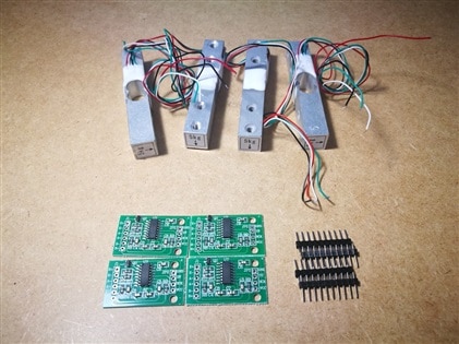
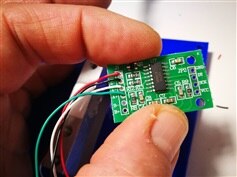
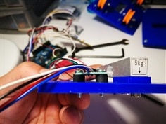
The first step was to find the right weight sensor and test its sensitivity. I should thank to michaelkellett that addressed me in the right direction; I bought a first series of four scale sensors in the weight range of 0-5 Kg and about half gram sensitivity for 3$/piece including the HX711 based amplifier circuit (the IC datasheet is in attach to the bottom of this post)

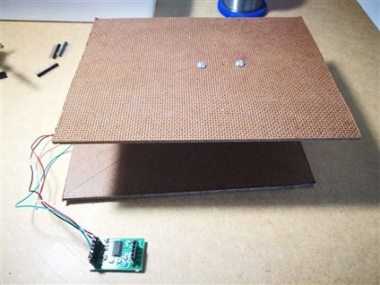
Using a 3 mm MDF sheet I have created a simple test sample to see the kind of data I should expect; after writing a few lines of code to show the readings on the serial terminal from an Arduino UNO I got a satisfying result and I definitely adopted this hardware solution.
The filament roll scale design
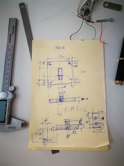
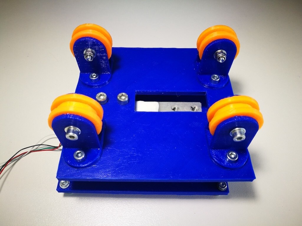
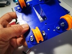
Recycling the idea of my 3D printer filament spool holder design I have made the design of a compact scale supporting a rotating filament roll as shown in the images below. As shown in the 3D representation the filament roll lies on the four wheels that rotates free and the support is connected to the base through the scale sensor.
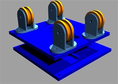

One support can be entirely built 3D printing 22 pieces with some M3 and M4 Allen screws and nuts at a very low price
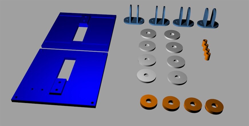
Assembling the parts
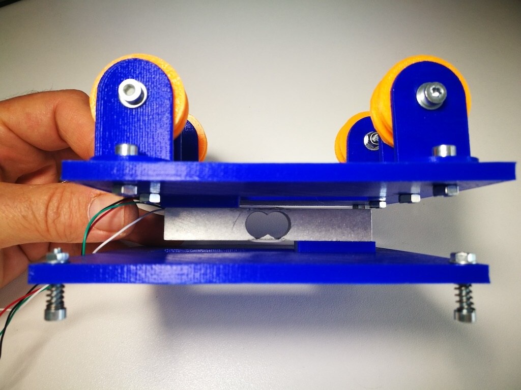
After all the 22 pieces has been printed can be easily assembled together. The top and bottom surfaces will be the filament spool support and the weight material scale at the same time. The filament is tensioned by the extruder so the roll should be free to rotate lying on the four free wheels (the orange ones). As shown in the assembly steps in the image gallery below top and bottom sides of the support are joined through the load sensor. It should be in the range 5-10 Kg max to support the filament roll that weight between 1,5 Kg and 2,5Kg (2Kg plastic rolls).
| {gallery} Scale roll support parts and assembly |
|---|
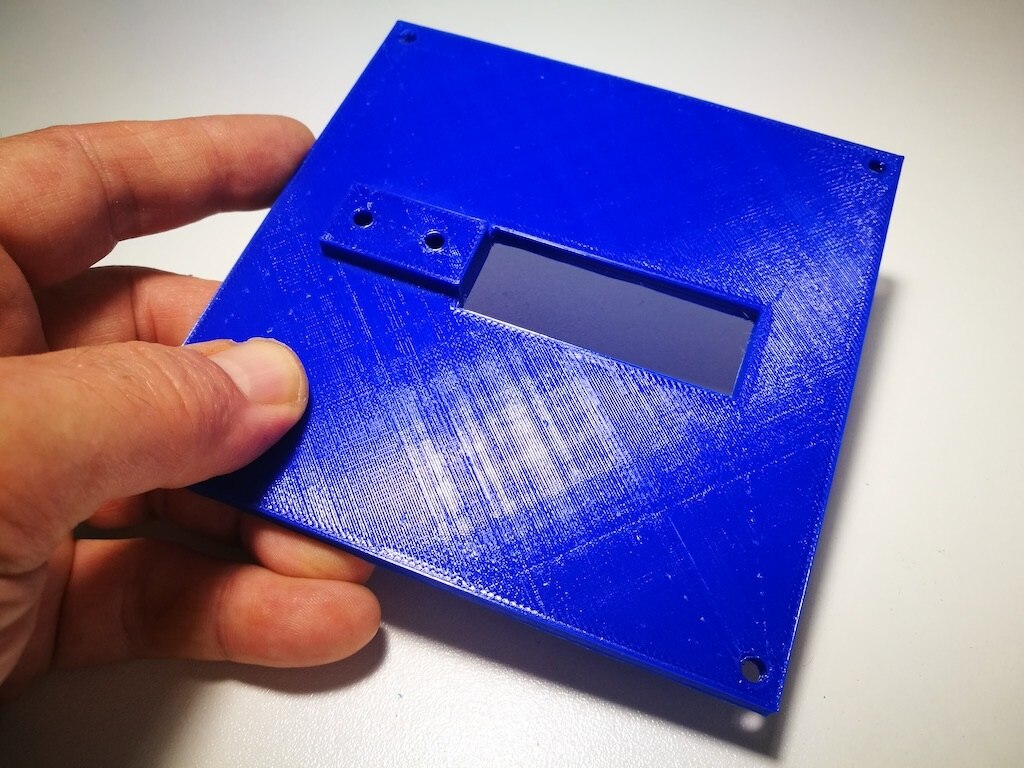
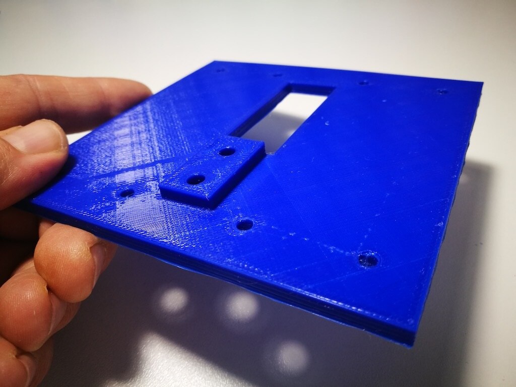
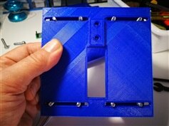
3D printed base |
3D printed top |
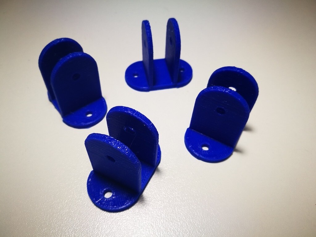
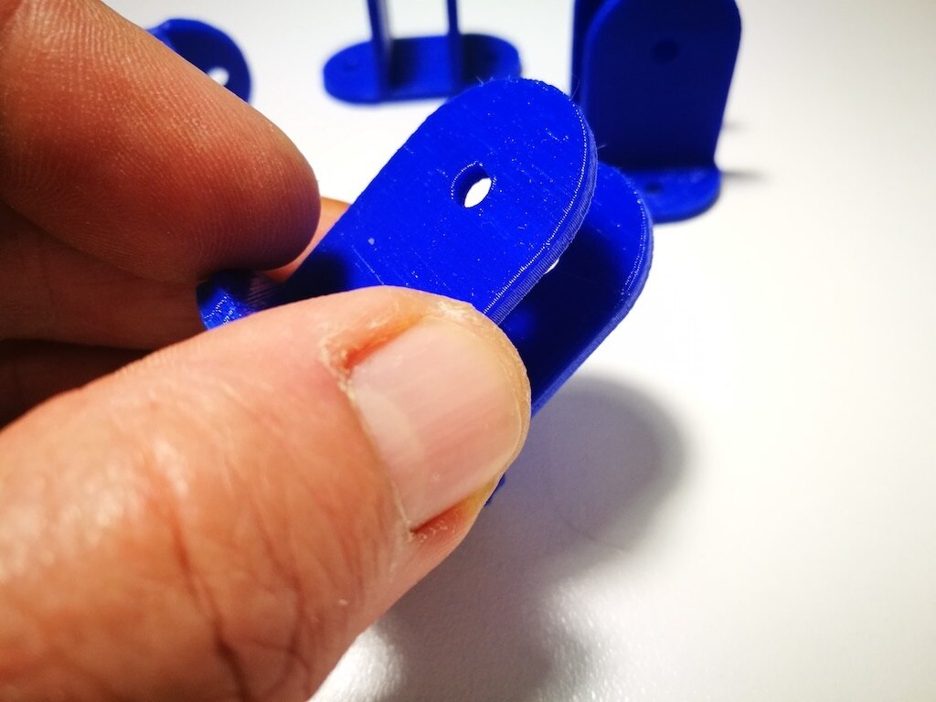
The free wheels supports |
The free wheel supports |
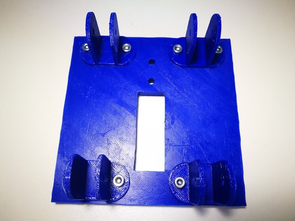
The free wheel supports mounted on the top part |
The top part with the free wheels assembled |
Free wheel detail (top support) |
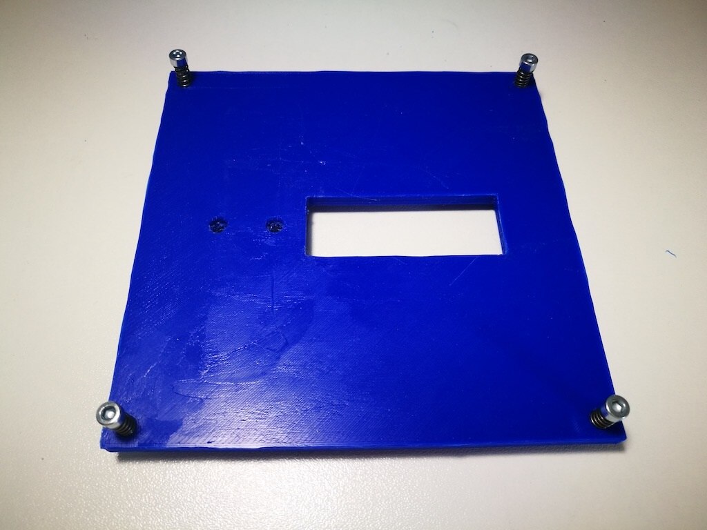
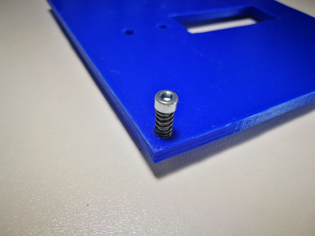
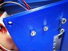
The base with the four calibration screws, top view |
The base with the four calibration screws, bottom view |
Calibration screw with spring of the base |
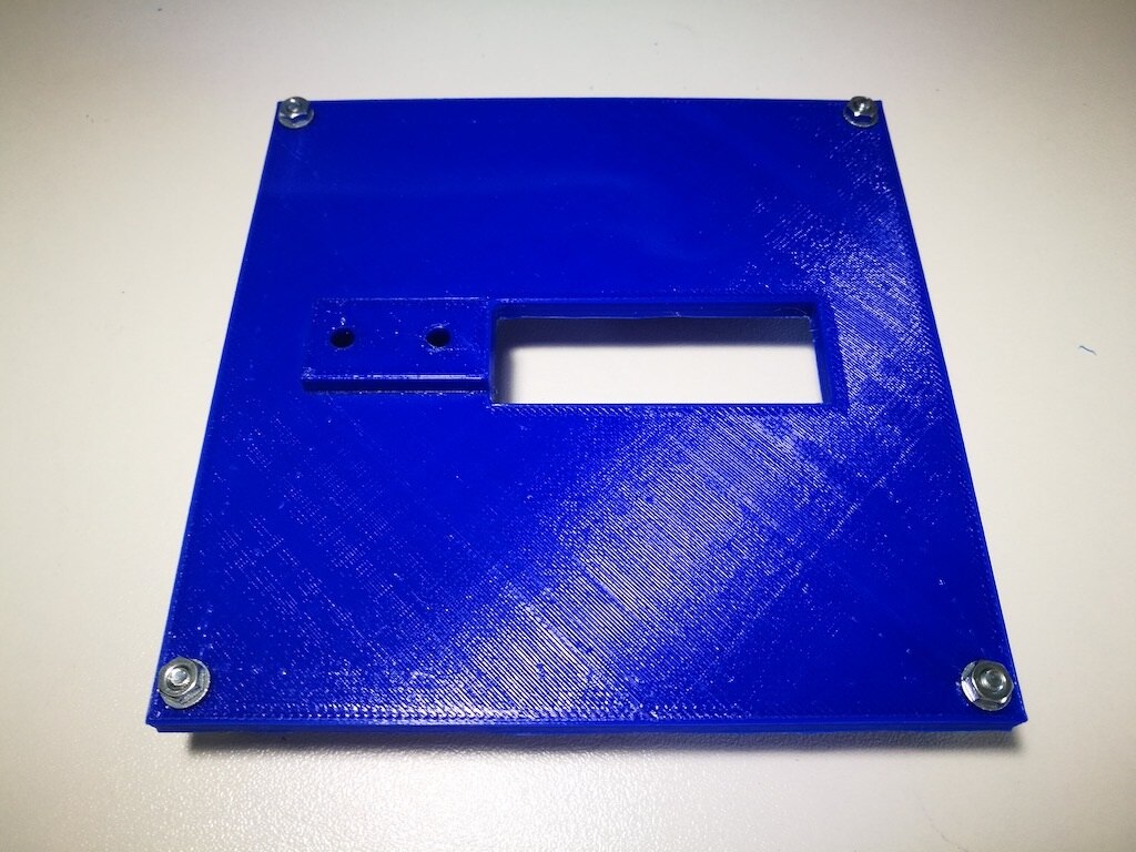
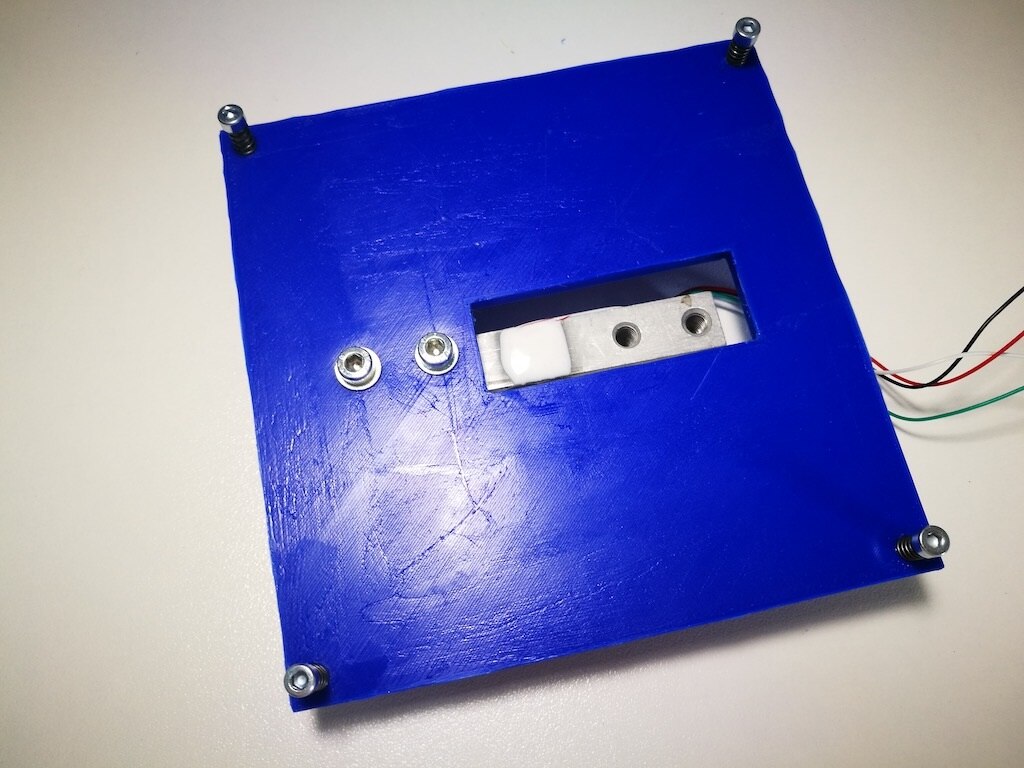
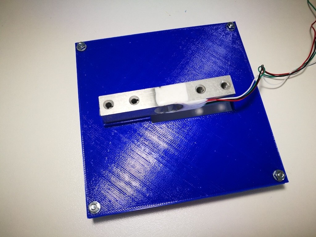
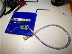
The base with the load sensor mounted, bottom view |
The base with the load sensor mounted, top view |
Base and load sensor assembled |
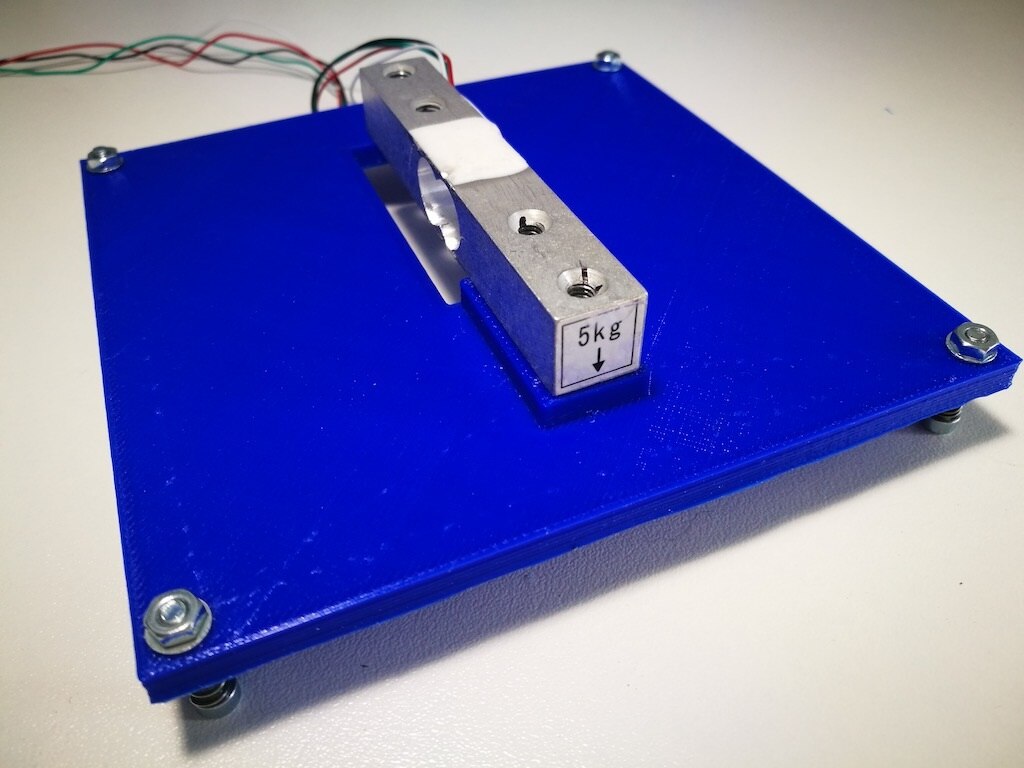
The top support mounted on the base through the load sensor |
The final assembly side view |
Testing the support 3D printing |
Testing the support 3D printing |


Some structure improvements
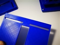
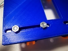
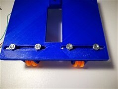
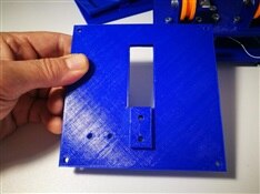
Testing the first version of the 3D printed scale I saw that filament rolls can have different spool dimensions, also if the same weight. To manage the different widths between spools (may depends on different providers or different production batches) the top base design has been update; now it is possible to set the position of the four free wheels supports as shown in the images below.
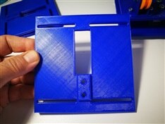
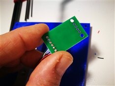
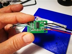
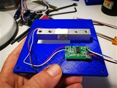
The wires coming from the load sensor are very thin and delicate so I decided that it was too risky to add a connector do I decided to include in the scale building also the HX711 filter adding two holes to the bottom part to fix the small IC board.
Circuit and wiring
The image below shows the functional design of the circuit and the interface

As the filament is usually available in two different dimensions, 1.75 and 3 mm diameter, the rolls are available in different weights and we should consider using at least two kinds of materials it was necessary to provide a three dip switch to select these three settings before starting the system. Making the first experiments I saw tat it was impossible to distinguish automatically the three phases when a 3D print job starts:
1. Power the system and initialise it (calculating the empty tare without the filament)

2. Place the filament roll and wait the weight stabilises
3. Start reading the usage (material load)
(consumption can be expressed in grams or centimeters)

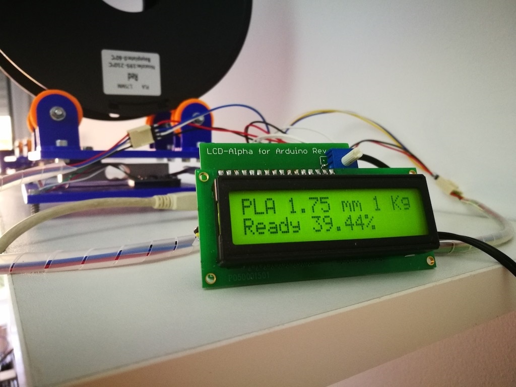
I have added two push buttons; an action button to manually set the three phases and a measure unit switch to select the visualisation on the display: filament units in grams or in centimeters/meters.
To have a complete status of the hardware a 3mm orange LED blink during every weight reading cycle while for the display I have used a shift register display (the full documented project is in these two articles: Enrico Miglino on ElectroSchematics.com and Arduino 16x2 LCD Shift Register Library - Part 2 ) based on 74HC595 shift-in register I have built in past to reduce the usage of Arduino pins.
As the MC711 already generates a digital signal only two pins are needed to connect it to the Arduino board.
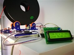
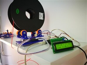
The project in action
The video below shows the first prototype and the final building in action after software filtering calculations have been included in the building.
The initial part of the video shows how connecting the sensor only without controls, due to unpredictable weight fluctuations it is almost impossible to control the three phases mentioned above while the second part shows the final version accordingly with the wiring scheme.
The software
The Arduino sketch is built in two parts for better readability: an header file defining all the constants used by the calculations as well as the pin settings and the source functions in the .ino file. All the project is distributed under the LGPL 3.0 license and is available on GitHub: https://github.com/alicemirror/3DPrinterFilamentMonitor-LCD
Additional libraries added to the sketch are the bodge MX711 library fo manage the scale IC and the updated library for the shift-LCD fixed compatible with the last versions of Arduino IDE, available in attach to this post.
| hx711_datasheet.pdf | |

Top Comments