


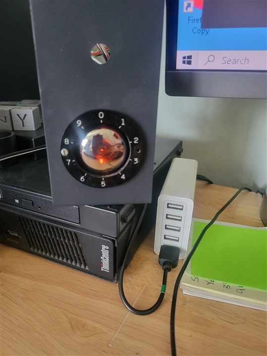
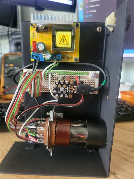
Just a fun simple project using the Arduino Beetle and a Z502 Dekatron tube to create a simple spinner out of this classic display tube. The design of the circuit was adapted from the circuit diagram I attached from "Dekatron Drive Basics M. Moorrees". The circuit is close to what is shown except for I changed Q1 and Q2 to optocouplers and the high voltage supply is slightly different.
More information on the Arduino Beetle can be found here: https://www.theengineeringprojects.com/2020/12/introduction-to-arduino-beetle.html

const int buttonRedPin = 4;  // the number of the pushbutton pin
const int buttonBluPin = 8;  // the number of the pushbutton pin
const int ledGrnPin = 10;    // the number of the LED pin
const int ledYelPin = 11;    // the number of the LED pin
int guideMS = 50;
const int stepMS = 900;

// variables will change:
int buttonRedState = 0;  // variable for reading the pushbutton status
int buttonBluState = 0;  // variable for reading the pushbutton status

void setup()
{
  Serial.begin(9600);
  // initialize the LED pin as an output:
  pinMode(ledGrnPin, OUTPUT);
  pinMode(ledYelPin, OUTPUT);
  // initialize the pushbutton pin as an input:
  pinMode(buttonRedPin, INPUT);
  pinMode(buttonBluPin, INPUT);
}

void loop() {
  Serial.print("guideMS  ");
  Serial.println(guideMS);

  buttonRedState = digitalRead(buttonRedPin);

  if (buttonRedState == HIGH)
    {
    guideMS = guideMS + 10;
    }

  buttonBluState = digitalRead(buttonBluPin);

  if (buttonBluState == HIGH)
    {
    guideMS = guideMS - 10;
    }

  digitalWrite(ledYelPin, HIGH);
  delay(guideMS);
  digitalWrite(ledGrnPin, HIGH);
  delay(guideMS);
  digitalWrite(ledYelPin, LOW);
  delay(guideMS);
  digitalWrite(ledGrnPin, LOW);
  delay(stepMS);


}

