


A stepper motor is an electric motor that moves in discrete steps. Each step is a fraction of a full rotation, and the motor's position can be controlled precisely without the need for feedback systems. This makes stepper motors highly useful in applications requiring precise positioning and repeatability such as robotics joints and arms, automotive, CNC Machines, etc.
The digital nature of their control signals (typically pulses) makes interfacing with microcontrollers straightforward. In this tutorial we will be controlling a 28BYJ-48 stepper motor using a ULN2003 driver and an Arduino. This tutorial will guide you through the process step-by-step to get your motor spinning.
Table of Contents
- How Stepper Motors Work
- What is the 28BYJ-48 Stepper Motor?
- Features
- 28BYJ-48 Stepper Motor Pinout
- Hardware Components
- Software
- ULN2003 Stepper Motor Driver Board
- ULN2003 Driver Board Pinout
- Wiring – Connecting 28BYJ-48 Stepper Motor and ULN2003 Driver Board to Arduino UNO
- Basic Arduino Example Code to Control a 28BYJ-48 Stepper Motor Using Stepper Library
How Stepper Motors Work
Stepper motors work based on the principle of electromagnetism. They consist of multiple coils that are organized in phases. Here’s a simplified overview of their operation:
-
Construction: A typical stepper motor consists of a rotor (the part that moves) and a stator (the stationary part). The rotor is made of permanent magnets or soft iron, while the stator is made of coils.
-
Electromagnetic Interaction: When the coils in the stator are energized in a specific sequence, they create magnetic fields. These fields attract or repel the magnets on the rotor, causing it to move.
-
Stepping Sequence: The sequence in which the coils are energized determines the direction and the step size. By alternating the current through the coils, the motor can make precise steps.
-
Control Methods:
- Full-Step: All coils are energized sequentially to make one step at a time.
- Half-Step: Coils are energized partially or in combinations to create half-steps, providing smoother movement.
- Microstepping: Coils are energized in a way that allows for very small steps, leading to extremely smooth motion and high resolution.
What is the 28BYJ-48 Stepper Motor?
The 28BYJ-48 is a small, inexpensive stepper motor widely used in electronics projects due to its ease of use and low cost.
Features
- Compact Size: The 28BYJ-48 is small, making it suitable for space-constrained applications.
- Gear Reduction: The built-in gearbox increases the torque and reduces the speed, which is beneficial for applications requiring high torque at low speeds.
- Unipolar Configuration: It has five wires and operates in a unipolar configuration, simplifying the control circuitry.
28BYJ-48 Stepper Motor Specifications
- Operating Voltage: 5V DC
- Step Angle: 5.625°
- Stride Angle: 0.08789°
- Frequency: 100Hz
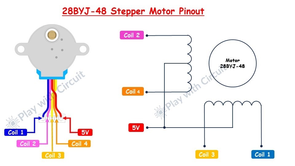
28BYJ-48 Stepper Motor Pinout
The pin configuration is as follows:
- Blue Wire: Coil 1
- Pink Wire: Coil 2
- Yellow Wire: Coil 3
- Orange Wire: Coil 4
- Red Wire: VCC (5V)
Hardware Components
- 28BYJ-48 Stepper Motor
- ULN2003 Driver Board
- Arduino UNO R3
- Jumper Wires
- Breadboard
- 5V power supply
- USB cable type A/B
Software
- Arduino IDE: Download and install the Arduino Integrated Development Environment (IDE) from Arduino's official website.
ULN2003 Stepper Motor Driver Board
Microcontrollers like Arduino typically output a maximum current of around 20-40 mA per I/O pin, which is insufficient to drive a stepper motor directly. So we need a motor driver to run the motor.
The ULN2003 driver can handle higher currents and higher voltages, making it suitable for driving the coils of the stepper motor. It acts as a buffer between the microcontroller and the stepper motor, allowing the microcontroller to control the motor without being damaged by the higher currents required.
ULN2003 Driver Board Pinout
It has several pins and connectors that facilitate its connection to a microcontroller and the stepper motor. Here’s a detailed explanation of the pinout:
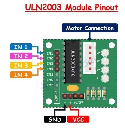
1. Power Pins
- VCC: This pin is used to provide power to the driver board and the stepper motor. It typically requires a 5V power supply, which is often supplied from the microcontroller or an external power source.
- GND: This is the ground pin and should be connected to the ground of the microcontroller and the power supply.
2. Input Pins (IN1 to IN4)
These are the control input pins that connect to the digital output pins of a microcontroller (e.g., Arduino). They receive signals to control the stepper motor.
- IN1 (Input 1): Connects to a digital output pin on the microcontroller to control the first coil of the stepper motor.
- IN2 (Input 2): Connects to a digital output pin on the microcontroller to control the second coil of the stepper motor.
- IN3 (Input 3): Connects to a digital output pin on the microcontroller to control the third coil of the stepper motor.
- IN4 (Input 4): Connects to a digital output pin on the microcontroller to control the fourth coil of the stepper motor.
3. Motor Connector
The driver board has a 5-pin connector that matches the connector on the 28BYJ-48 stepper motor. This connector simplifies the wiring process.
Wiring – Connecting 28BYJ-48 Stepper Motor and ULN2003 Driver Board to Arduino UNO
Here is the circuit diagram
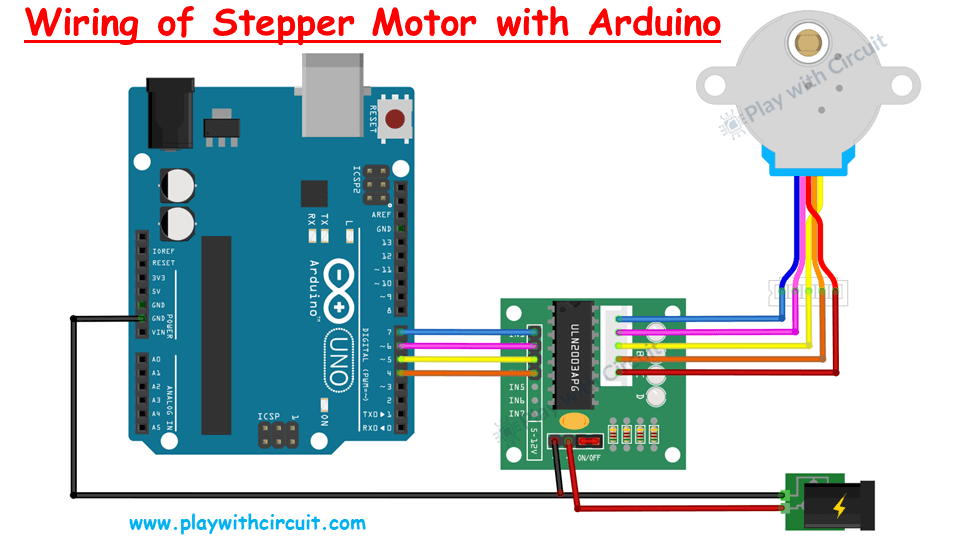
ULN2003 and 28BYJ-48 to Arduino Connections
- Motor Connections: Connect the 5-pin connector from the stepper motor to the ULN2003 driver board.
- Power Connections: Connect external 5V power supply to the ULN2003 driver, and the GND pin of the supply to the GND pin of driver and Arduino.
- Control Connections: Connect the IN1, IN2, IN3, and IN4 pins on the ULN2003 board to digital pins 7, 6, 5, and 4 on the Arduino, respectively.
Basic Arduino Example Code to Control a 28BYJ-48 Stepper Motor Using Stepper Library
#include <Stepper.h>
//define Input pins of the Motor
#define OUTPUT1   7                // Connected to the Blue coloured wire
#define OUTPUT2   6                // Connected to the Pink coloured wire
#define OUTPUT3   5                // Connected to the Yellow coloured wire
#define OUTPUT4   4                // Connected to the Orange coloured wire
// Define the number of steps per rotation
const int stepsPerRotation = 2048;  // 28BYJ-48 has 2048 steps per rotation in full step mode as given in data sheet
// Initialize the stepper motor with the sequence of control pins OUTPUT1, OUTPUT3, OUTPUT2, IN4
// OUTPUT1 and OUTPUT3 are connected to one coil and OUTPUT2 and OUTPUT4 are connected to one Coil
Stepper myStepper(stepsPerRotation, OUTPUT1, OUTPUT3, OUTPUT2, OUTPUT4);
void setup() {
  // Set the speed of the motor in RPM (adjust as needed)
  myStepper.setSpeed(15);  // 15 RPM
}
void loop() {
  // Rotate in One Direction and complete one complete rotation i.e 2048 steps
  myStepper.step(stepsPerRotation);
  delay(1000);  // Delay between rotations
  // For Rotation in opposite direction provide the variable to the parameter with negative Sign
  myStepper.step(-stepsPerRotation);
  delay(1000);  // Delay between rotations
}
If you want to learn more about how to program the Arduino to rotate stepper motor without using any librarary in full-step mode, half step mode then check out this tutorial: Control 28BYJ-48 Stepper Motor with ULN2003 Driver and Arduino
Start your next electronics adventure with Arduino! To see the full lineup of arduino products such as boards, kits, and accessories, head over to our online stores.
