


An Open-Source platform to create digital devices and interactive objects that sense and control physical devices. | Arduino Tutorials | |
| Arduino Projects |
This project is an entry in the Build a Smarter World MKR Fest.
The challenge is to build a practical and useful system based on an arduino MKR 1300.
My plan is to build the MKR 1300 into a platform with a set of useful interfaces that allow it to be adapted to many applications.
The core interfaces will be:
- a LoRa radio to enable low cost long range communications
- a GPS receiver (with UART interface) to track the location of the system and provide an accurate time
- a low-power SPI LCD to display graphics and text
- an I2C Grove interface to connect any serial Grove module
- 2 analog Grove interfaces to connect any analog Grove sensors
- a digital Grove interface to connect any digital grove module
These interfaces and connectors will be implemented on a custom PCB that results in a clean compact system platform.
Application systems will be packaged in 3D printed cases tailored to accommodate the necessary features.
The first application, which is the subject of this project, will be a geo-locator system that can send GPS location data to a LoRa gateway.
This system will initially be used to explore the reach of the LoRa radio.
Some of the applications where I might use this geo-location capability include:
- I generally don't have my cell phone turned on, so this may be used to show where I am or where my car is.
- It could be used to show when I am getting close to arriving at home.
- It can show how far away my ride is when someone is coming to pick me up after work, so I don't have to hover around the door.
- It could be used to tell me to turn my cell phone on - take it out of airplane mode.
The range of the radio will dictate which applications can be useful or how useful they will be.
Part of this initial project will be to explore ways to maximize range of the radio.
Unboxing
Here is an unboxing video showing the kit supplied by element14. It also shows the design of the custom interconnect PCB designed for the platform:
The 915 MHz antennas I purchased claim to have 5 dBi gain.
Update 1 - PCB and LCD
The interconnect PCB came back from the printer in 9 days so I put some connectors on it, connected an SPI LCD and wrote a little program to check out that it works properly. It is always fun when a PCB works properly
Update 2 - GPS & LCD
This update adds GPS to the MKR platform. Right now I am just displaying latitude, longitude and altitude to test the GPS and display. The digits after the decimal point on latitude and longitude have been zeroed just for the video. In the final system both displays will show the distance between the modules, the elevation of both modules and the received signal strength of both modules. The information being transmitted bidirectionally via LoRa will be latitude, longitude, altitude, and received signal strength. This information will allow me to explore the range capabilities of LoRa and the factors that affect it.
The project is proceeding well. All add-on electronics are working under software control. Now it just a matter of getting the radios communicating and then packaging the modules prior to running some field tests.
Update 3 - Mechanical Packaging
I got the LoRa radios communicating but because the antennas cables are so delicate, I decided I better package the systems before proceeding to integrate LoRa communications and GPS data transfer. The packaging design took more effort than expected so it has been a while since my last update. This video is a quick view of the packaging and how it goes together:
Now that I can pick the devices up without stressing the cables and connectors, I can get back to working on the software.
Then I can start having fun testing system performance and local communication range.
Update 4 - LoRa Communications
I have been really struggling to get the software working - my software issues, not the development system, but it has taken far to many hours to get this far. However the LoRa geo-location system is fully operational now. Here is a video showing the two units communicating GPS and signal strength data:
I have tried walking round the neighborhood out to 783 meters and it never lost connection, even through many houses and a hill. So it does not need direct line-of-sight.
Now that the platforms are fully functional, the next step is to take one on a drive and see how far away it can still make contact. The system is all set up to display the distance between units as well as the altitude of both units and the received signal strength of both units. This way I will know how high I have to be to make contact and how far away I can connect.
Update 5 - LoRa Range Test
I took the LoRa GPS system out for a spin in my car today. Here are a few pictures:
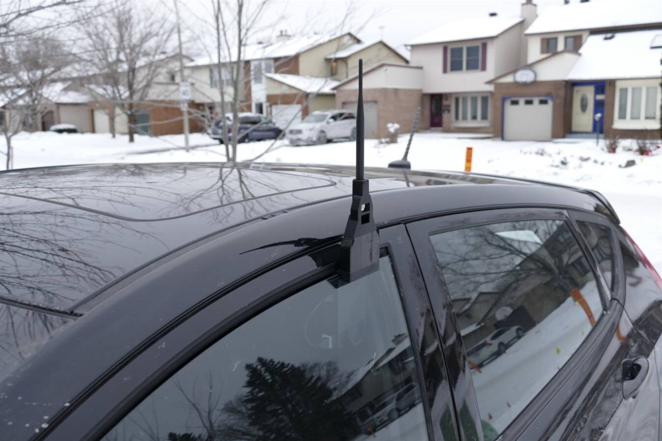
This picture shows the LoRa GPS module mounted on the driver's side window.
Getting the design angles right was a bit tricky, partly because taking measurements at cold temperatures with bare hands is problematic.
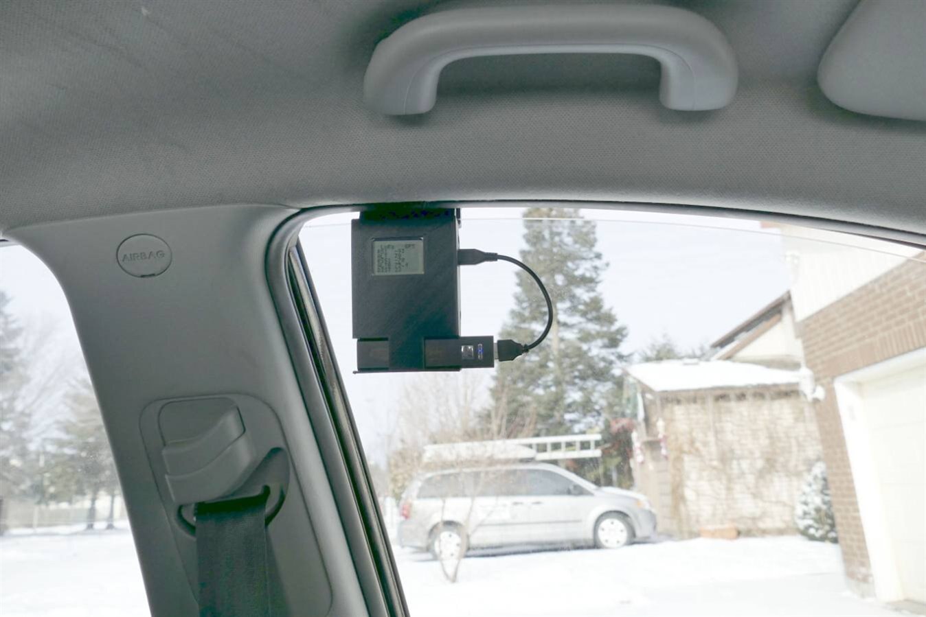
This is what the unit looks like from inside the car.
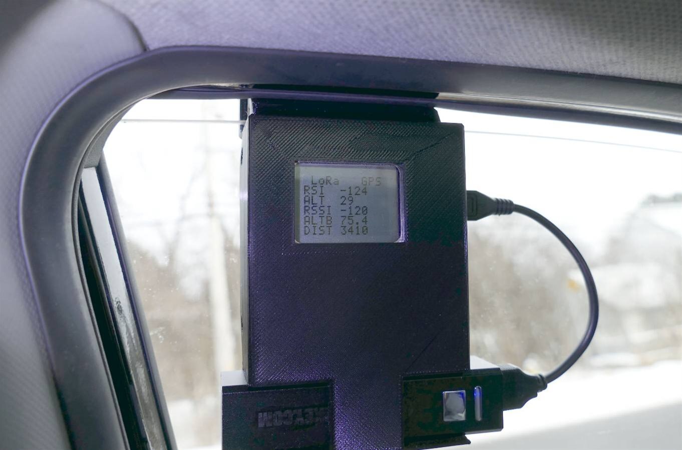
Here is a picture at 3.4 km from my house. The signal was pretty good out to 1 km even though there was lots of houses preventing direct line-of-sight. The signal dropped out a couple of times between 1 km and 3.4 km. There is never a clear line-of-sight to my house on this route . The spot where this image was taken is slightly elevated, but also does not have a clear line-of-sight to my house. There are a bunch of trees and buildings between this location and my house.
Clearly this LoRa radio has much longer range than WiFi, but it still benefits from a direct line-of-sight transmission if one can be arranged.
I plan to try some longer range connections, but they may have to wait for spring as the local mountain lookout is closed during winter.
Update 6
I decided to do a quick comparison between LoRa RF power and cell phone RF power.
Here is the video showing LoRa transmits less RF power than a cell phone:
The LoRa RF power was higher than I expected, but still significantly lower than a cell phone.
All of these measurements are pretty near field and I don't know anything about the cell phone or meter polarizations.
Here is the Arduino code for the LoRa GeLo MKR - for those that want to know how not to write code....
  /*
 * LoRa GeLo MKR - Long Range Geo-Locator MKR 1300
 * Reads GPS location and altitude. Calculates distance to home base from GPS coordinates.
 * Displays distance, altitude and RSSI data on an LCD.
 * by Doug Wong   2018
 */
#include <TinyGPS++.h>
#include <SPI.h>
#include <LoRa.h>
#define PIN_SCE   6       //chip select pin for LCD
#define PIN_RESET 10      //reset pin for LCD
#define PIN_DC    7       //data / command select pin for LCD
#define PIN_SDIN  8       //serial data input pin for LCD (MOSI)
#define PIN_SCLK  9       //SPI clock pin for LCD
#define LCD_C     LOW     //this value select command mode on LCD DC
#define LCD_D     HIGH    //this value select data mode on LCD DC
#define LCD_X     84      //number of pixels on an LCD line
#define LCD_Y     48      //number of vertical pixels on LCD


TinyGPSPlus gps;
const unsigned long SEND_INT = 5000;         // Sends a msg on this interval (milliSec)
const unsigned long LISTEN_TIME = 200;       // Listens for a response for this interval (milliSecs)
unsigned long numMsgs = 0;                   // Number of messages sent
unsigned long lastSend = 0;                  // Time of last message sent (milliSecs)
char latitude[14];                           // GPS latitude
char longitude[14];                          // GPS longitude
char altitudes[14];                          // GPS altitude
char gpslats[6];
char gpslongs[6];
char gpsalts[6];
char rsi[6];                     // received signal strength at home base
char LoRaIn;                     // character received via LoRa
char LoRaInStr[2];
char distl[4];
char distr[4];
char loopc[6];
char LoRaChar;
char LoRaString[1];
double gpslat;
double gpslong;
double gpsalt;
double lat1;                       // latitude of this device
double lat2 = 45.42;               // default latitude of home base
double lon1;                       // longitude of this device
double lon2 = -75.6;               // default longitude of home base
double gpsdist;                    // distance to home base
double xpos;
double ypos;
double rad =  6371000;
int gpslati;
int gpslongi;
int gpsalti;
int rssi;                          // recieved signal strength
int packetSize;
int disti;
int distj;
int loops;
double p = 0.017453292519943295;      // Pi/180


// pixel map of character set for LCD
static const byte ASCII[][5] =
{
 {0x00, 0x00, 0x00, 0x00, 0x00} // 20
,{0x00, 0x00, 0x5f, 0x00, 0x00} // 21 !
,{0x00, 0x07, 0x00, 0x07, 0x00} // 22 "
,{0x14, 0x7f, 0x14, 0x7f, 0x14} // 23 #
,{0x24, 0x2a, 0x7f, 0x2a, 0x12} // 24 $
,{0x23, 0x13, 0x08, 0x64, 0x62} // 25 %
,{0x36, 0x49, 0x55, 0x22, 0x50} // 26 &
,{0x00, 0x05, 0x03, 0x00, 0x00} // 27 '
,{0x00, 0x1c, 0x22, 0x41, 0x00} // 28 (
,{0x00, 0x41, 0x22, 0x1c, 0x00} // 29 )
,{0x14, 0x08, 0x3e, 0x08, 0x14} // 2a *
,{0x08, 0x08, 0x3e, 0x08, 0x08} // 2b +
,{0x00, 0x50, 0x30, 0x00, 0x00} // 2c ,
,{0x08, 0x08, 0x08, 0x08, 0x08} // 2d -
,{0x00, 0x60, 0x60, 0x00, 0x00} // 2e .
,{0x20, 0x10, 0x08, 0x04, 0x02} // 2f /
,{0x3e, 0x51, 0x49, 0x45, 0x3e} // 30 0
,{0x00, 0x42, 0x7f, 0x40, 0x00} // 31 1
,{0x42, 0x61, 0x51, 0x49, 0x46} // 32 2
,{0x21, 0x41, 0x45, 0x4b, 0x31} // 33 3
,{0x18, 0x14, 0x12, 0x7f, 0x10} // 34 4
,{0x27, 0x45, 0x45, 0x45, 0x39} // 35 5
,{0x3c, 0x4a, 0x49, 0x49, 0x30} // 36 6
,{0x01, 0x71, 0x09, 0x05, 0x03} // 37 7
,{0x36, 0x49, 0x49, 0x49, 0x36} // 38 8
,{0x06, 0x49, 0x49, 0x29, 0x1e} // 39 9
,{0x00, 0x36, 0x36, 0x00, 0x00} // 3a :
,{0x00, 0x56, 0x36, 0x00, 0x00} // 3b ;
,{0x08, 0x14, 0x22, 0x41, 0x00} // 3c <
,{0x14, 0x14, 0x14, 0x14, 0x14} // 3d =
,{0x00, 0x41, 0x22, 0x14, 0x08} // 3e >
,{0x02, 0x01, 0x51, 0x09, 0x06} // 3f ?
,{0x32, 0x49, 0x79, 0x41, 0x3e} // 40 @
,{0x7e, 0x11, 0x11, 0x11, 0x7e} // 41 A
,{0x7f, 0x49, 0x49, 0x49, 0x36} // 42 B
,{0x3e, 0x41, 0x41, 0x41, 0x22} // 43 C
,{0x7f, 0x41, 0x41, 0x22, 0x1c} // 44 D
,{0x7f, 0x49, 0x49, 0x49, 0x41} // 45 E
,{0x7f, 0x09, 0x09, 0x09, 0x01} // 46 F
,{0x3e, 0x41, 0x49, 0x49, 0x7a} // 47 G
,{0x7f, 0x08, 0x08, 0x08, 0x7f} // 48 H
,{0x00, 0x41, 0x7f, 0x41, 0x00} // 49 I
,{0x20, 0x40, 0x41, 0x3f, 0x01} // 4a J
,{0x7f, 0x08, 0x14, 0x22, 0x41} // 4b K
,{0x7f, 0x40, 0x40, 0x40, 0x40} // 4c L
,{0x7f, 0x02, 0x0c, 0x02, 0x7f} // 4d M
,{0x7f, 0x04, 0x08, 0x10, 0x7f} // 4e N
,{0x3e, 0x41, 0x41, 0x41, 0x3e} // 4f O
,{0x7f, 0x09, 0x09, 0x09, 0x06} // 50 P
,{0x3e, 0x41, 0x51, 0x21, 0x5e} // 51 Q
,{0x7f, 0x09, 0x19, 0x29, 0x46} // 52 R
,{0x46, 0x49, 0x49, 0x49, 0x31} // 53 S
,{0x01, 0x01, 0x7f, 0x01, 0x01} // 54 T
,{0x3f, 0x40, 0x40, 0x40, 0x3f} // 55 U
,{0x1f, 0x20, 0x40, 0x20, 0x1f} // 56 V
,{0x3f, 0x40, 0x38, 0x40, 0x3f} // 57 W
,{0x63, 0x14, 0x08, 0x14, 0x63} // 58 X
,{0x07, 0x08, 0x70, 0x08, 0x07} // 59 Y
,{0x61, 0x51, 0x49, 0x45, 0x43} // 5a Z
,{0x00, 0x7f, 0x41, 0x41, 0x00} // 5b [
,{0x02, 0x04, 0x08, 0x10, 0x20} // 5c ¥
,{0x00, 0x41, 0x41, 0x7f, 0x00} // 5d ]
,{0x04, 0x02, 0x01, 0x02, 0x04} // 5e ^
,{0x40, 0x40, 0x40, 0x40, 0x40} // 5f _
,{0x00, 0x01, 0x02, 0x04, 0x00} // 60 `
,{0x20, 0x54, 0x54, 0x54, 0x78} // 61 a
,{0x7f, 0x48, 0x44, 0x44, 0x38} // 62 b
,{0x38, 0x44, 0x44, 0x44, 0x20} // 63 c
,{0x38, 0x44, 0x44, 0x48, 0x7f} // 64 d
,{0x38, 0x54, 0x54, 0x54, 0x18} // 65 e
,{0x08, 0x7e, 0x09, 0x01, 0x02} // 66 f
,{0x0c, 0x52, 0x52, 0x52, 0x3e} // 67 g
,{0x7f, 0x08, 0x04, 0x04, 0x78} // 68 h
,{0x00, 0x44, 0x7d, 0x40, 0x00} // 69 i
,{0x20, 0x40, 0x44, 0x3d, 0x00} // 6a j
,{0x7f, 0x10, 0x28, 0x44, 0x00} // 6b k
,{0x00, 0x41, 0x7f, 0x40, 0x00} // 6c l
,{0x7c, 0x04, 0x18, 0x04, 0x78} // 6d m
,{0x7c, 0x08, 0x04, 0x04, 0x78} // 6e n
,{0x38, 0x44, 0x44, 0x44, 0x38} // 6f o
,{0x7c, 0x14, 0x14, 0x14, 0x08} // 70 p
,{0x08, 0x14, 0x14, 0x18, 0x7c} // 71 q
,{0x7c, 0x08, 0x04, 0x04, 0x08} // 72 r
,{0x48, 0x54, 0x54, 0x54, 0x20} // 73 s
,{0x04, 0x3f, 0x44, 0x40, 0x20} // 74 t
,{0x3c, 0x40, 0x40, 0x20, 0x7c} // 75 u
,{0x1c, 0x20, 0x40, 0x20, 0x1c} // 76 v
,{0x3c, 0x40, 0x30, 0x40, 0x3c} // 77 w
,{0x44, 0x28, 0x10, 0x28, 0x44} // 78 x
,{0x0c, 0x50, 0x50, 0x50, 0x3c} // 79 y
,{0x44, 0x64, 0x54, 0x4c, 0x44} // 7a z
,{0x00, 0x08, 0x36, 0x41, 0x00} // 7b {
,{0x00, 0x00, 0x7f, 0x00, 0x00} // 7c |
,{0x00, 0x41, 0x36, 0x08, 0x00} // 7d }
,{0x10, 0x08, 0x08, 0x10, 0x08} // 7e ←
,{0x78, 0x46, 0x41, 0x46, 0x78} // 7f →
};


void LcdCharacter(char character)                       // display a character on the LCD
{
  LcdWrite(LCD_D, 0x00);                                // display a blank space before character
  for (int index = 0; index < 5; index++)               // font uses 5 x 7 pixels
  {
    LcdWrite(LCD_D, ASCII[character - 0x20][index]);    // display next column of pixels for this character
  }
  LcdWrite(LCD_D, 0x00);                                // display a blank space after character
}


void LcdClear(void)                                     // display a blank screen
{
  LcdWrite(LCD_C, 0x40 );                               // command to set Y cursor position to 0
  LcdWrite(LCD_C, 0x80 );                               // command to set X cursor position to 0
  for (int index = 0; index < LCD_X * LCD_Y / 8; index++)
  {
    LcdWrite(LCD_D, 0x00);                              // display a blank column of 8 pixels
  }                                                     // the LCD automatically steps to the next position
}


void LcdInitialise(void)
{
  pinMode(PIN_SCE, OUTPUT);                                        // set the chip select pin to be an output
 // pinMode(PIN_RESET, OUTPUT);
  pinMode(PIN_DC, OUTPUT);                                         // set the DC pin to be an output
  pinMode(PIN_SDIN, OUTPUT);                                       // set the MOSI pin to be an output
  pinMode(PIN_SCLK, OUTPUT);                                       // set the SPI clock pin to be an output
 // digitalWrite(PIN_RESET, LOW);
 // digitalWrite(PIN_RESET, HIGH);
  LcdWrite(LCD_C, 0x21 );                                         // put LCD in Extended Commands mode.
  LcdWrite(LCD_C, 0x80 );                                         // Set LCD Vop (Contrast). 0x80 - 0xFF
  LcdWrite(LCD_C, 0x04 );                                         // Set Temp coefficent. 0x04 - 0x07
  LcdWrite(LCD_C, 0x14 );                                         // LCD bias mode 1:48.  0x10 - 0x17
  LcdWrite(LCD_C, 0x20 );                                         // LCD Basic Commands
  LcdWrite(LCD_C, 0x0C );                                         // put LCD back in normal mode.
}


void LcdString(char *characters)                        // display a sting of characters on LCD
{
  while (*characters)
  {
    LcdCharacter(*characters++);
  }
}


void LcdWrite(byte dc, byte data)                       // display a byte as 8 vertical pixels
{
  digitalWrite(PIN_DC, dc);                             // control the DC pin - should be data
  digitalWrite(PIN_SCE, LOW);                           // apply chip select to LCD
  shiftOut(PIN_SDIN, PIN_SCLK, MSBFIRST, data);         // send byte as serial bit stream
  digitalWrite(PIN_SCE, HIGH);                          // deselect LCD
}


void setup() {
  Serial.begin(115200);                                 // the serial port may be used for debugging

  delay(1000);
  Serial.println("LoRa Send and Listen started...");
  if (!LoRa.begin(915E6)) {
    Serial.println("LoRa start failed");
    while (1);
  }
  Serial1.begin(9600);                                  // this serial port is used for GPS communications


  LcdInitialise();                                      // display a splash screen
  LcdClear();
  LcdString("   ARDUNIO  ");
  LcdString("   MKR WAN  ");
  LcdString("  LORA  GPS ");
  LcdString("            ");
  LcdString("     by     ");
  LcdString("  DOUG WONG ");
  delay(1000);                                          // show the splash screen for 1 second
  LcdClear();                                           // clear the LCD


//  lat2 = 0;
//  lon2 = 0;
}
void loop()                         // main loop reads GPS sends via LoRa, calculates distance, reads RSSI, displays data
{
  while (Serial1.available() > 0)
  gps.encode(Serial1.read());


  if (gps.location.isUpdated())
  {

    gpslat = gps.location.lat();     // Latitude in degrees (double)
    gpslong = gps.location.lng();    // Longitude in degrees (double)
    gpsalt = gps.altitude.meters();  // Altitude in meters (double)


    lat2 = gpslat;
    lon2 = gpslong;
    lat1 = 45.42;
    lon1 = -75.6;
//    gpsdist = 12742 * asin(sqrt(0.5 - cos((lat2 - lat1) * p)/2 + cos((lat1 * p) * cos(lat2 * p) * (1 - cos((lon2 - lon1) * p)))/2));
//    gpsdist = acos(sin(lat1)*sin(lat2) + cos(lat1*PI/180) + cos(lat1*PI/180)*cos(lat2*PI/180)*cos(lon2*PI/180 - lon1*PI/180))*6371000;
//    xpos = (lon2-lon2)*cos((lat2-lat1)/2);
// Calculate distance to home base from GPS data
    xpos = 2 * rad * tan((lon2-lon1)/2) * (90 - ((lat2-lat1)/2))/90;
    ypos = 2 * rad * tan((lat2-lat1)/2);
    gpsdist = sqrt(xpos*xpos + ypos*ypos);
    gpsalti = int(gpsalt);
    itoa(gpsalti,altitudes, 10);
    gpsalti = int((gpsalt - gpsalti) * 100);
    itoa(gpsalti, gpsalts, 10);
    disti = int(gpsdist/46.7);
    itoa(disti,distl, 10);
    distj = int((gpsdist - disti) * 1000);
    itoa(distj, distr, 10);
  }

  // Check to see if time to send another message
  if ((millis() - lastSend) > SEND_INT){
    lastSend = millis();
    numMsgs++;
    rssi = LoRa.packetRssi();
    LoRa.beginPacket();
    LoRa.print("R");
    LoRa.print(rssi);
    LoRa.print("     ");
    LoRa.print("A");
    LoRa.print(gpsalts);
    LoRa.print("     ");
    LoRa.print("D");
    LoRa.print(distl);
    LoRa.print("     ");
    LoRa.endPacket();


    itoa(rssi,rsi,10);
    LcdWrite(LCD_C, 0x80 );  // set X Command
    LcdWrite(LCD_C, 0x41 );  // set Y Command
    LcdString("RSI  ");
    LcdString(rsi);
    LcdString("   ");
    LcdWrite(LCD_C, 0x80 );  // set X Command
    LcdWrite(LCD_C, 0x42 );  // set Y Command
    LcdString("ALT  ");
    LcdString(gpsalts);
    LcdString("   ");
    LcdWrite(LCD_C, 0x80 );  // set X Command
    LcdWrite(LCD_C, 0x44 );  // set Y Command
    LcdString("ALTB 75.4");
    LcdWrite(LCD_C, 0x80 );  // set X Command
    LcdWrite(LCD_C, 0x45 );  // set Y Command
    LcdString("DIST ");
    LcdString(distl);
    LcdString("     ");
    LcdWrite(LCD_C, 0x80 );  // set X Command
    LcdWrite(LCD_C, 0x40 );  // set Y Command
    LcdString(" LoRa   GPS ");
    LcdWrite(LCD_C, 0x80 );  // set X Command
    LcdWrite(LCD_C, 0x43 );  // set Y Command
    LcdString("RSSI ");


    // Now listen for response
    while ((millis() - lastSend) < LISTEN_TIME){
      // try to parse packet
      int packetSize = LoRa.parsePacket();
      if (packetSize > 0){
        while (LoRa.available()){
          LoRaChar = (char)LoRa.read();
          Serial.print(LoRaChar);
          LoRaString[0] = LoRaChar;
          LcdString(LoRaString);
        }
      }
    }
    LcdString("  ");
    LoRa.flush();
  }
}
Project Wrap Up Notes
The MKR WAN 1300 platform packs powerful performance into a compact form factor, and despite my personal problems with programming, its development environment makes it easy to build applications.
The LoRa radio has better range than WiFi and lower RF power than a cell phone. It connects well out to about 1 km regardless of buildings and obstructions in the path, and it can connect much, much further if there is a direct line-of-sight.
The project involved learning more about LoRa, designing a custom PCB, designing system enclosures and of course software to make the system perform.
I am happy with the project result, the electronics perform well, the packaging fits and works well, and I find it very interesting to drive around monitoring signal strength versus distance and altitude.
This MKR system with LCD, GPS and LoRa is a great platform that I can use to develop lots more LoRa applications.
Update:
This project won a spectacular Arduino Engineering KitArduino Engineering Kit - here is the unboxing of the prize:
Thanks element14 and Arduino.
Related links:
Arduino | Upcoming MKR Livestreams, MKR Giveaways, and Arduino Engineering Kit Grand Prizes!
Top Comments