


Disclaimer: I’m an engineer, not a pro film maker. Be advised.
Disclaimer: I’m an engineer, not a pro film maker. Be advised.

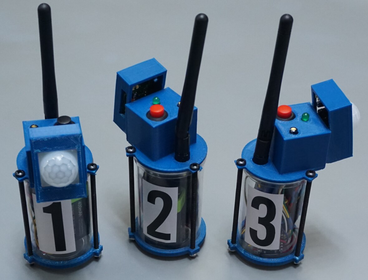
The wireless motion detector project. Three drop-modules report to the monitor in the foreground.
Motion detectors are cool but running wires out to them is a drag. We wanted to secure an area quickly and conveniently and without sirens or bells letting intruders know that we know that they are trespassing. That means no wires.
And so, it was decided, a wireless motion detecting system would be built.
We could picture it in our minds, a portable, self-contained system that would let us know when our parents got home or when Derek was breaching the perimeter around our couch-cushion fort. Derek doesn’t respect perimeters.
Design considerations – selecting components
We started with Arduino Micros and went from there. We chose these because they are small and have an on-board USB controller. This allows them to be programmed simply by plugging them into a USB port, just like the UNO. No FTDI adaptors would be needed like as is necessary for compact boards like the Arduino NANO. The version of the Micro used came without pin headers soldered on. This for ease of assembly and to conserve space. The pins would have been harder to solder to and would have taken up a lot more room.
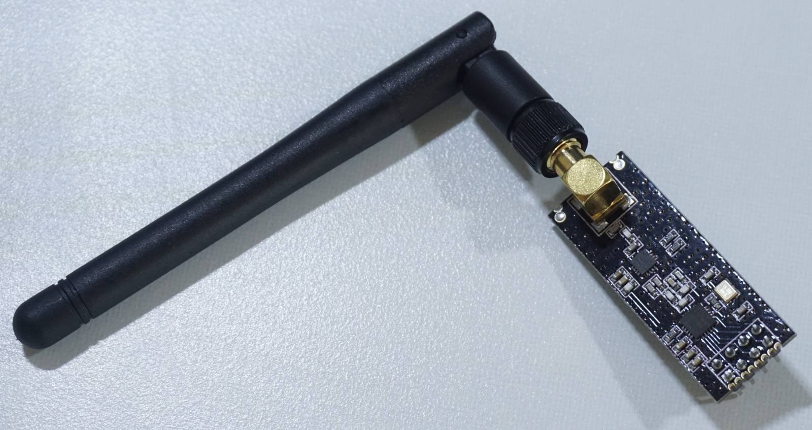
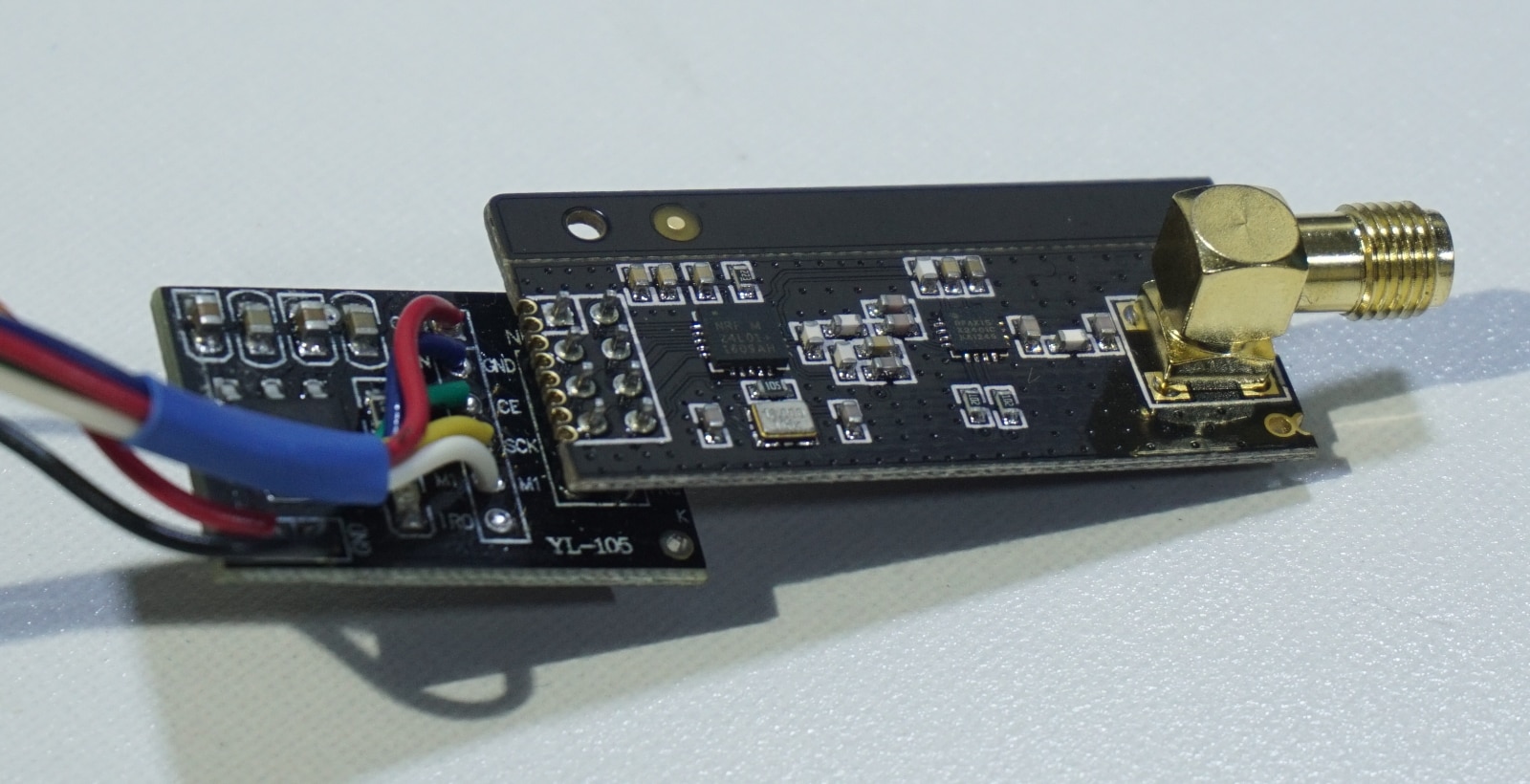
For the wireless bit, we selected the nRF24L01+ radios. Note the + at the end of the name. The “plus” models that have a male SMA connector for an external antenna and they have an alleged open-air range of 1000 meters when operated at maximum power.
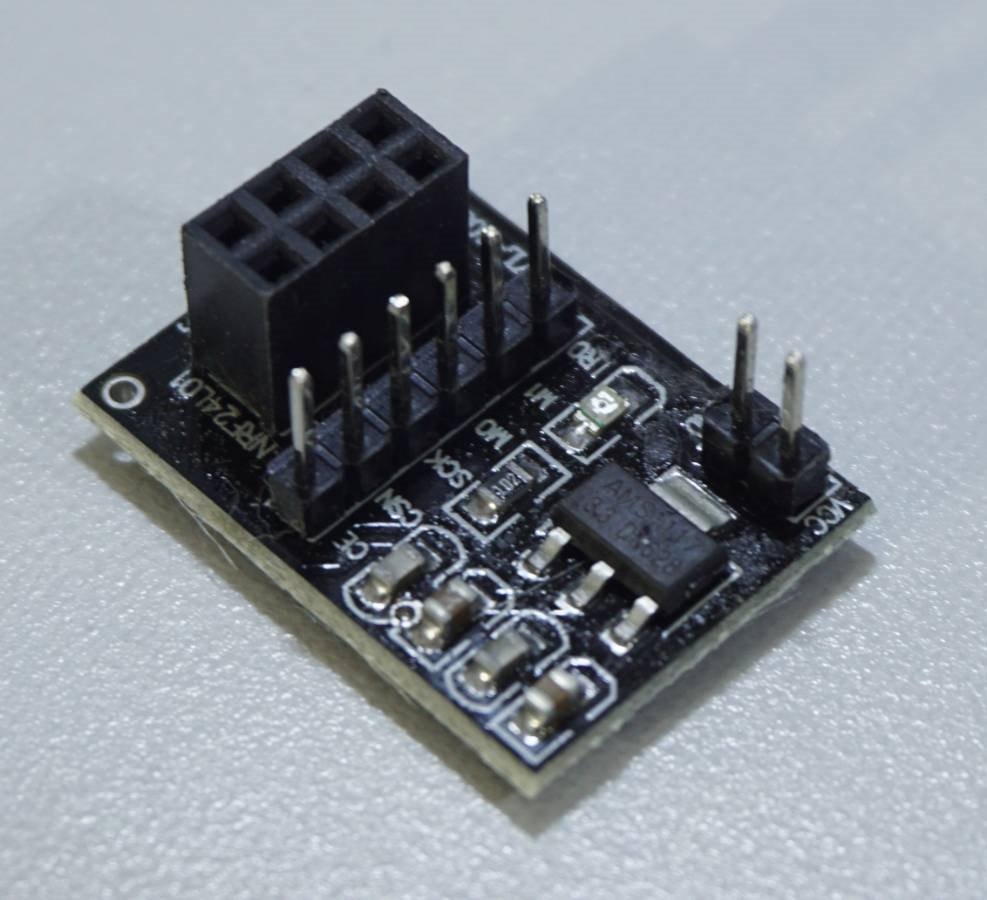
nRF24 radios are extremely finicky when it comes to their power. They do not tolerate supply noise at all. To put the stop to any issues of this sort before they start, we used an adapter board like this. They come with an AMS1117 linear regulator to keep the voltage to the radio at a steady 3.3 volts. They also have a few noise filtering capacitors to keep the power clean.
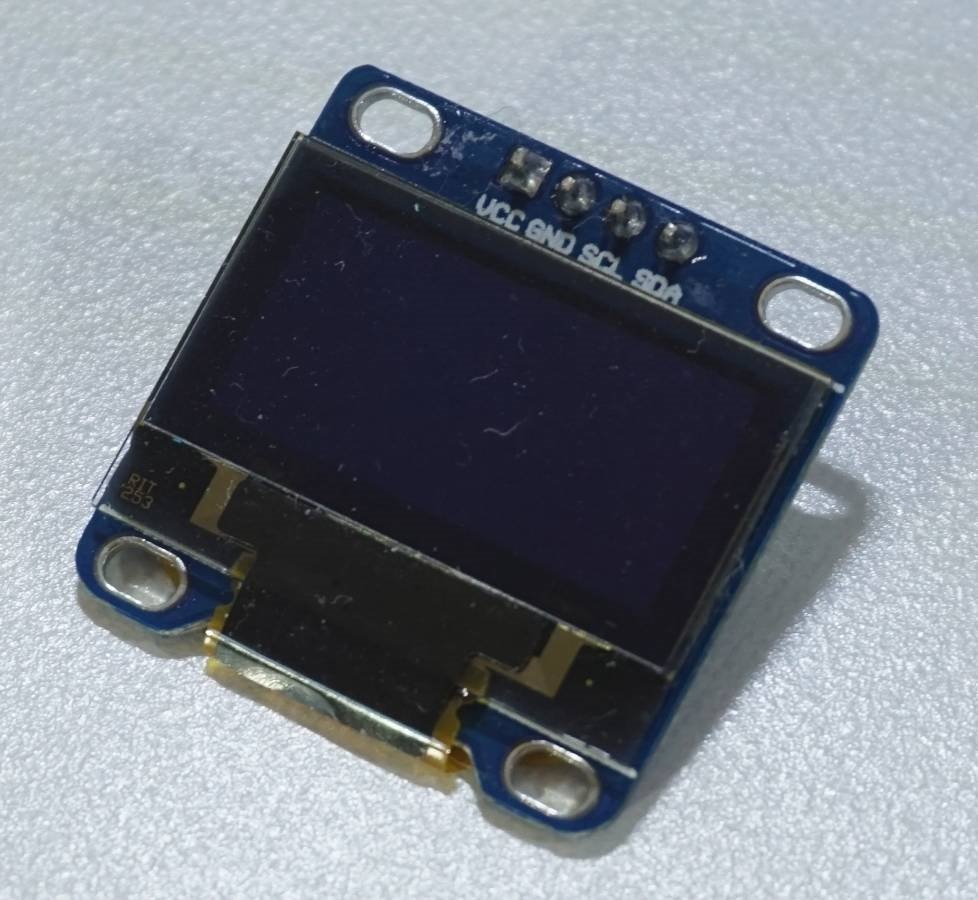
An 128x64 i2c OLED screen was used to display the status of the sensors. An i2c connection was chosen on purpose. The nRF24 radio communicates via SPI. So, to prevent any conflicts that might arise from having the screen and radio on the same data bus, it was decided use i2c for the screen. Yes, theoretically there should be no problem with putting the two devices on the same data bus. But all too often, reality swings in to ruin your day and you are left screaming about how everything worked fine on paper. To minimize any handholds for Murphy’s and Sod’s Law, communications to the screen and the radio were kept completely separate.
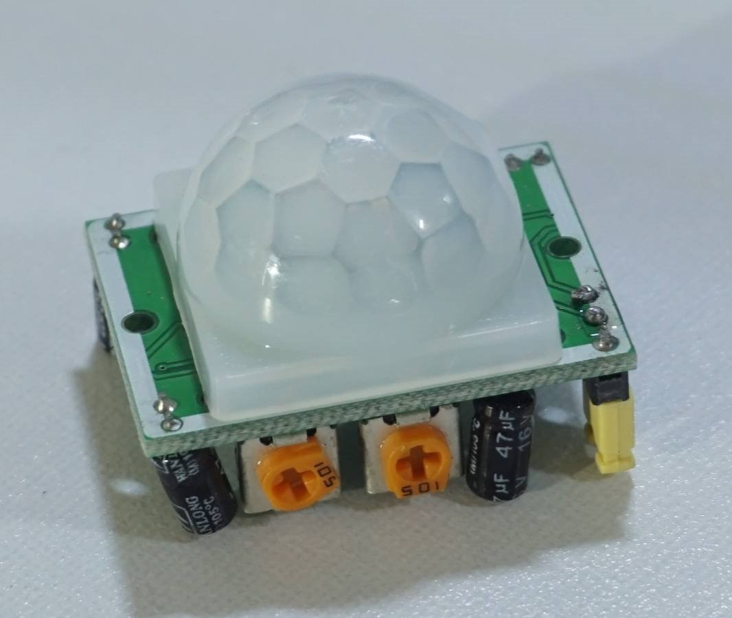
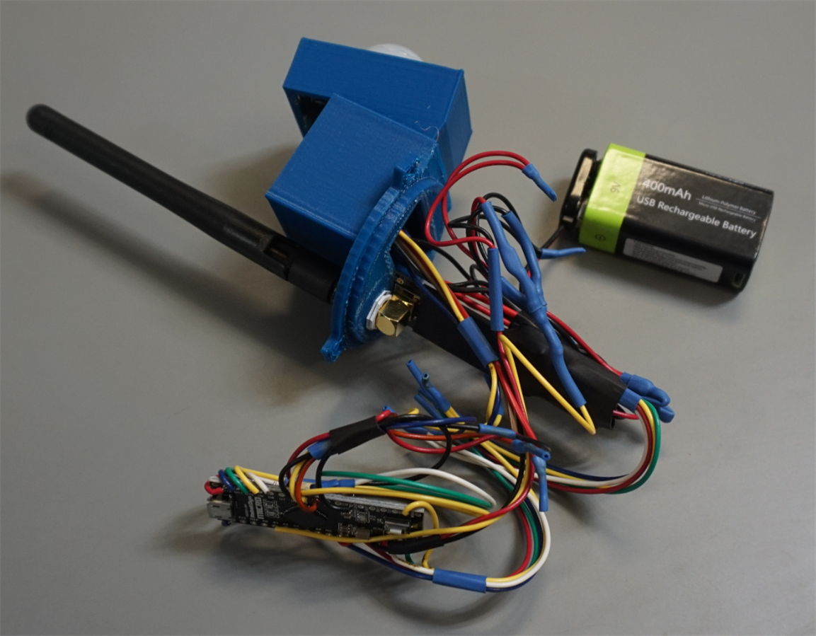
This is the PIR motion sensor used for the drop-modules. The potentiometers on the side control how sensitive the device is and how long the output stays high after motion is detected.
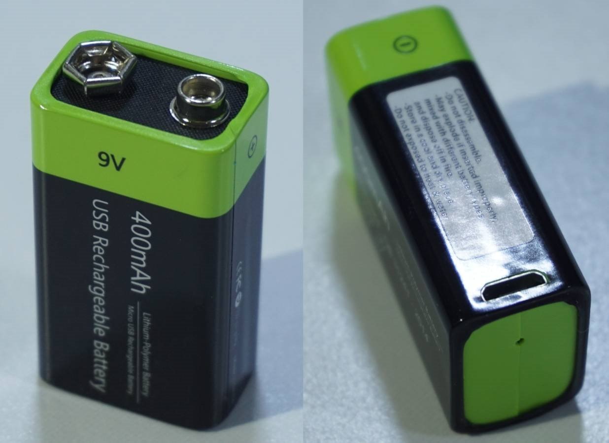
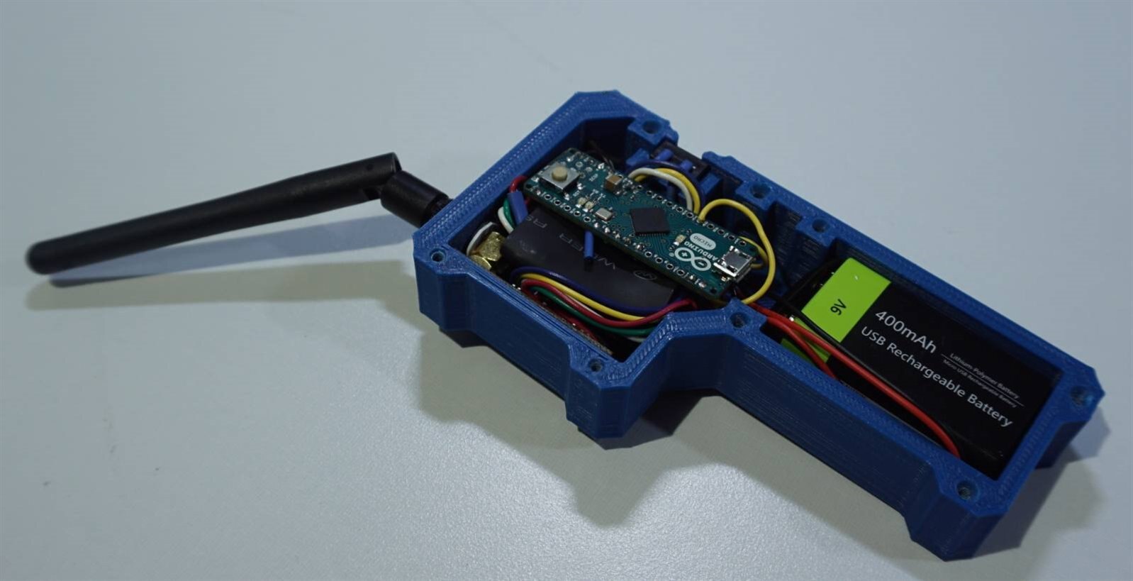
Lithium-polymer battery in the shape of 9-volt batteries was chosen as a power source for the drop-modules and the monitor. Originally, the intention was to use disposable alkaline or lithium 9-volt batteries. However, these types of batteries will not meet the power demands of the nRF24 radios. This point demands a bit of explanation. nRF24 radios draw very little “on” but quiescent. During the short period that they are transmitting their power requirement spikes abruptly. A typical 9-volt battery cannot provide the energy fast enough for the nRF24. This problem can sometimes be mitigated by installing a fairly large capacitor (100uF) in parallel with the battery. Another solution is to do what we did, use a lithium-polymer battery. The particular batteries we chose are very convenient for projects because they combine a lithium-polymer battery with a battery management circuit, a battery protection circuit, and a boost converter. They also have a micro USB port for charging. It’s like five components packed into the shape of a 9-volt battery. Note the tiny hole in the bottom of the battery. This is for a red LED that lights up when charging. The LED shuts-off when the battery is fully charged.
Monitor BOM
- - 1x – Arduino MICRO
- - 1x - nRF24L01+
- - 1x - nRF24L01 adapter board
- - 1x - 128x64 OLED i2c display
- - 1x - 9-volt form factor Li-Po battery
- - 1x – 9-volt battery clip
- - 3x - 6x6mm tactile NO button
- - 4x – 10kΩ resistor
- - 1x – on/off button
- - 8x - #2-56 x 1-inch screws
Drop-module BOM
- - 1x – Arduino MICRO
- - 1x - nRF24L01+
- - 1x - nRF24L01 adapter board
- - 1x - 9-volt form factor Li-Po battery
- - 1x – 9-volt battery clip
- - 1x – PIR sensor
- - 1x – tilt sensor
- - 1x – 5mm LED
- - 1x - 510Ω resistor (to limit current through the LED)
- - 4x – 10kΩ resistor
- - 1x – on/off button
- - 3x - #6-32 x 3.25” machine screws
- - 3x - #6-32 nuts
The Code (Attached to this article)
Code was written up for the drop modules and the monitor. The code for each of the drop modules is identical. During the drop-module’s setup routine, the address selection pins are polled to see what the modules address is. Two modules cannot have the same address. If they did, the monitor will interpret all the received data as coming from the same drop-module, and the system will not work as intended.
An ad-hoc protocol was developed for communicating drop-module status back to the monitor. The drop-modules encapsulate all of their data into an unsigned long variable. Each byte of this variable would represent a specific alarm code or the status of the battery. Then, the entire unsigned long variable is sent to the monitor.
At the monitor, this variable is broken back down into bytes, and the data is used to determine what drop-modules are active, what its status is and if the signal from any module is dropped.
The code for the drop-modules and the monitor share a number of details. They both us the RF24.h library to handle interactions with the radios. Also, they both use the TimerOne.h library. Timer one is used to make sure events like transmitting status and updating the OLED display happen at regular intervals.
The monitor uses the U8g2 library to control the OLED. This library is very easy to use, and it is loaded with easy to use functions for drawing lines and shapes and placing text on the screen. There is a huge selection of fonts to choose from too.
At a glance, the code, especially the monitor code looks complicated but don’t let it scare you. It is lengthy, but you have a couple things going for you. It is commented extensively, and it is written out in a longhand of sorts. This makes the code take up a lot more space than it needs to, but it is also easier to understand for the less experienced coder. Oh, and the bulk of the monitor code is subroutines used to refresh the OLED display.
The mechanical design (Files needed for 3D printing, attached to this article)
All the parts that we knew were going into the project were mocked-up in SolidWorks. The Arduino Micro, the nRF24, the 9-volt battery, the OLED screen. These mock-ups are mostly rough geometric approximations of the real parts. We don’t need a high level of detail to effectively design enclosures for the project.
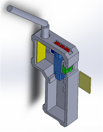
From here the enclosure for the monitor was drawn up. The enclosure takes style cues from sources like the Aliens movies and the short videos of Neill Blomkamp.
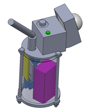
Then the drop-module was drawn up. It is designed around a clear plastic toothpick container. The container is clear and just the right size to house all the parts.
Putting it all together
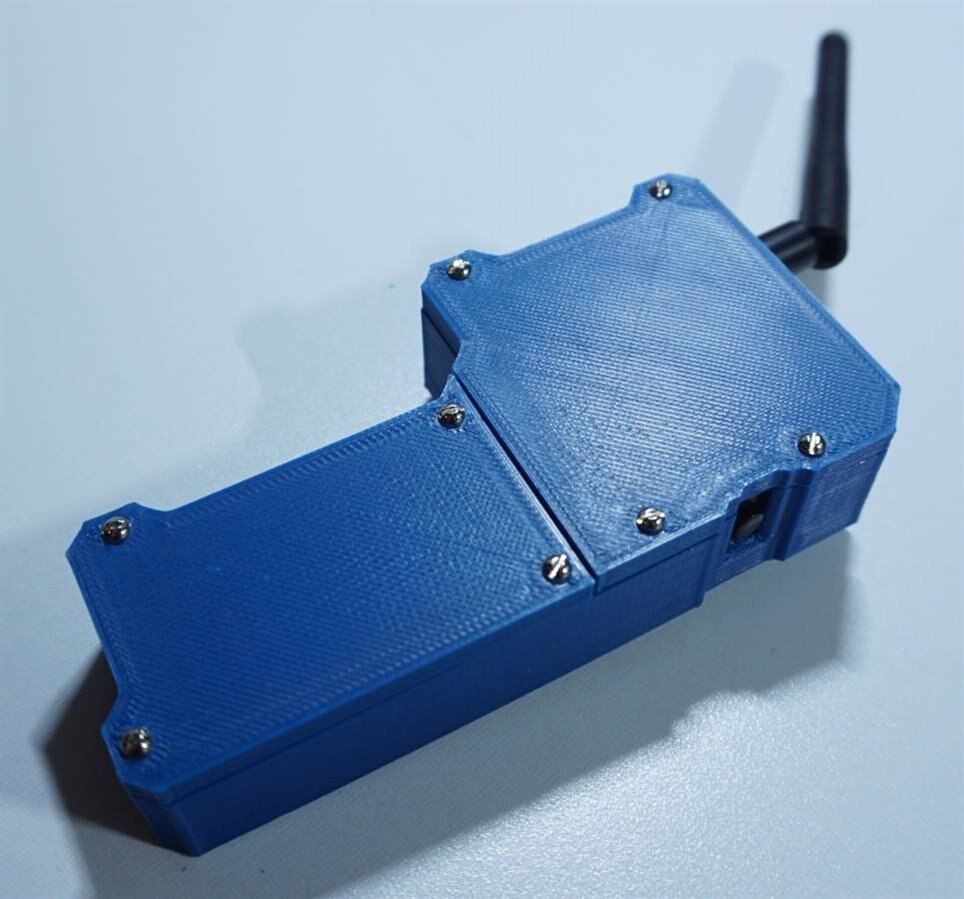
The monitor enclosure and the parts for the drop-modules were 3D printed in a pleasing dark blue color. There was nothing very complicated about the build. The components were wired together with short leads, soldered and then covered with heat-shrink tubing. The notable points of the build are illustrated in the pictures below.
The monitor
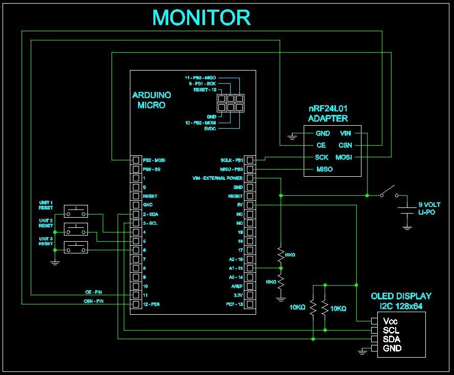
The monitor wiring diagram. Start here.
| {gallery:autoplay=false} Monitor Assembly |
|---|
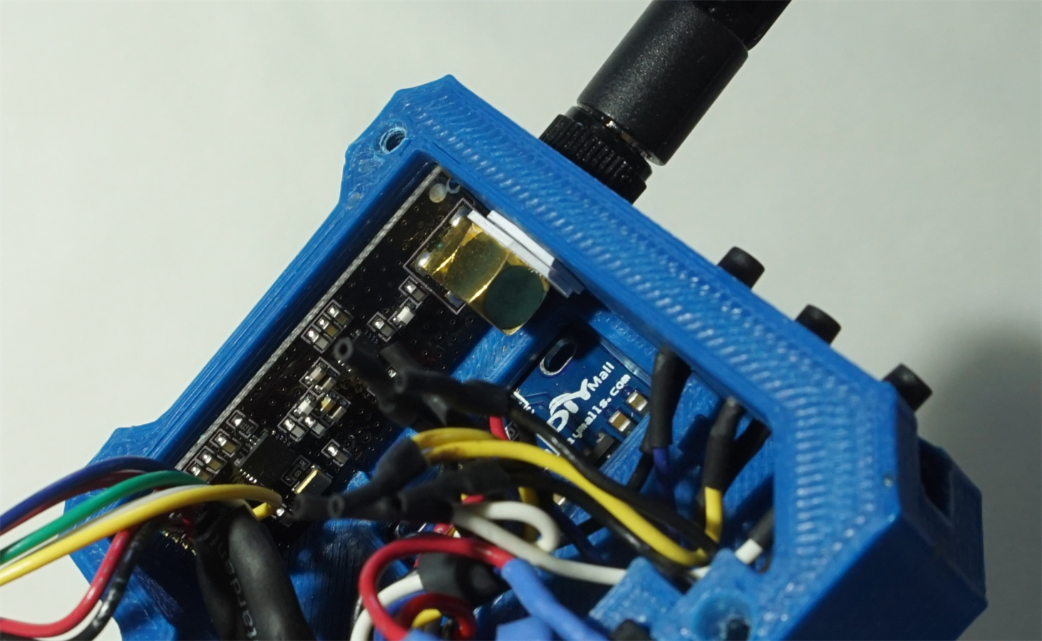
Here is the radio installed in the monitor. Notice the two spacers around the SMA connector. These keep the radio square to the interior surface when the antenna is threaded on - they were made by trimming an old credit card into washer shape with a hobby knife. |
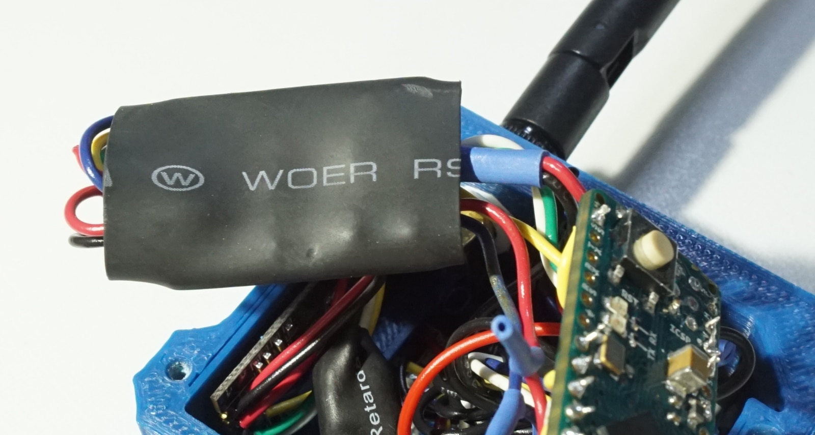
The pins and headers were de-soldered from the adapter board; this was done to conserve space. Then, wires were soldered to the adapter and then the whole board was covered with a big piece of heat-shrink tubing. |
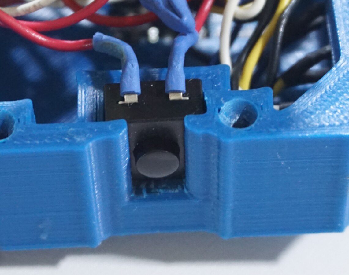
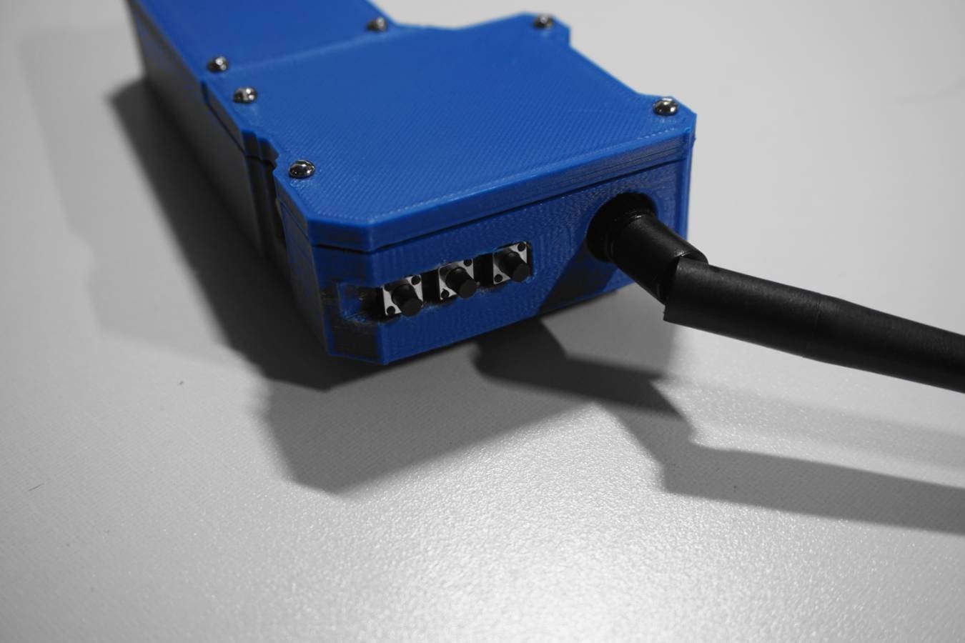
The on-off switch slides into the pocket designed to hold it. |
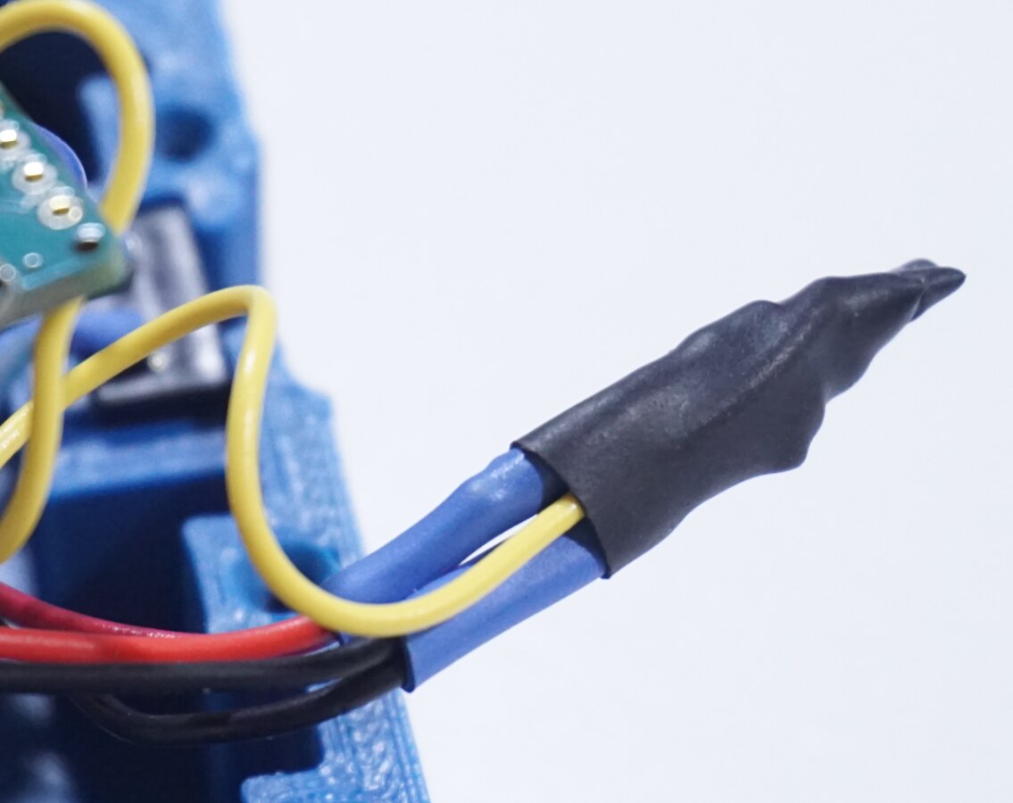
The voltage divider network for monitoring the battery status was constructed with a pair of 10k resistors. The entire assembly was covered in heat-shrink - the yellow wire runs to and ADC input on the Arduino MICRO. |
The reset buttons are pressed into their slots. Friction keeps them in place. |
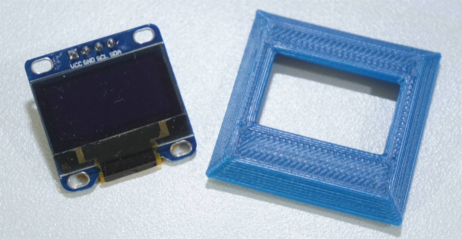
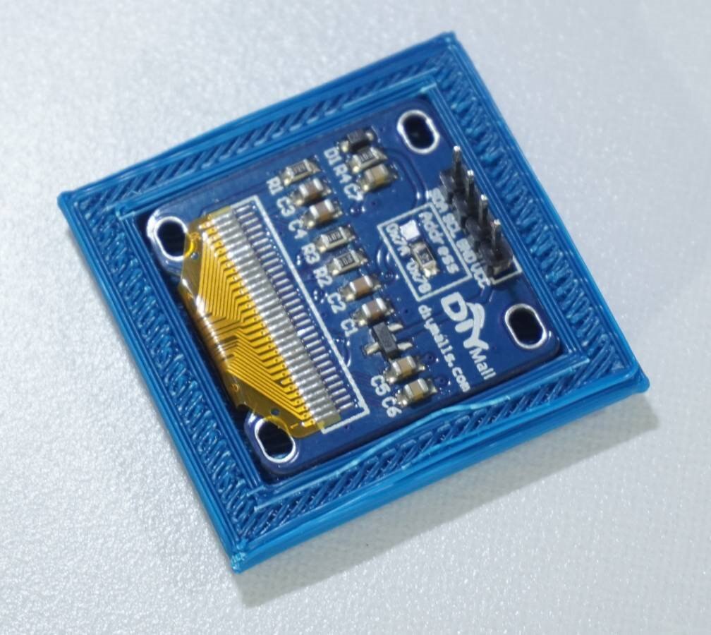
The conserve space, the OLED screen sits in a 3D printed bezel. |
The screen drops right into the rear of the bezel. |
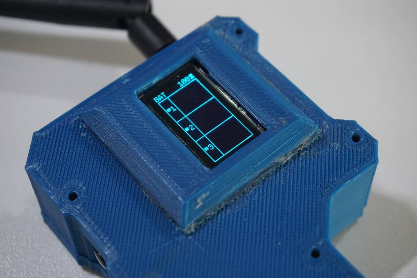
The screen installed on the outside of the monitor enclosure. |
Fold everything into the enclosure - be careful not to break anything. |
Once everything is tucked inside the monitor, fasten the rear covers down with #2 machine screws. |
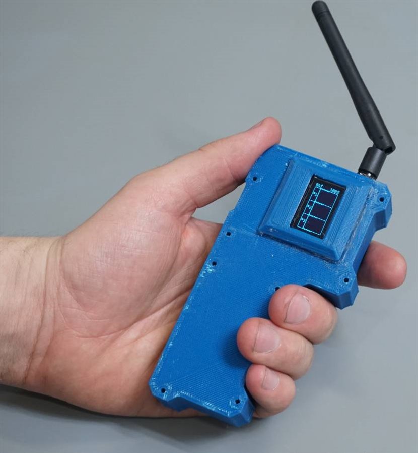
Completed monitor - human hand for scale. |
Building the drop-modules
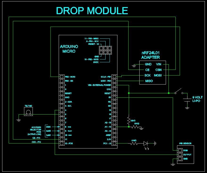
The schematic for the drop modules. Notice the address selection pins 8, 9, and 10. To set the address of the module, a single pin must be connected to ground. Modules cannot share addresses.
| {gallery} Building the drop module |
|---|
The drop modules are assembled with the same methods as the monitor - you can see here that all the components are wired up and protected with heat-shrink tubing. |
You can see here where the headers and pins have been de-soldered from the adapter board and the nRF24 and wire leads have been soldered in their place - the assembly is covered in heat-shrink after soldering. |
The PIR sensor is hot-glued into its 3D printed shell. |
To finish, carefully fold the everything into the containers and seat the tops. Then Slide the retaining ring over the bottom of the containers. Finally, fasten everything together with the long #6-32 screws and nuts. It is a good idea to label the drop-modules too. |

How to use it all
Conclusion
There were a lot of different ways we could have come at this project. We could have used a mesh network that would have allowed for dozens or over a hundred drop-modules, but instead, we went with three. Also, the code could have been written far more efficiently. Especially the monitor code. For anyone who attempts this project we strongly suggest having a go at optimizing the code.
We used 3D printed parts and toothpick containers to house our project, but you don’t have to do any of that. Use breadboards and cardboard. Or use plastic food containers. It doesn’t matter. The code and the hardware are oblivious to how good (or bad) they look. Also, for your version of this project, you can use different sensors. You don’t have to use PIR motion detectors. You could use the drop-modules to keep an eye on anything. Use photoresistors to see if someone turns on a light. Replace the PIR sensor with a momentary pushbutton or a pressure sensitive doormat to make a wireless doorbell. Maybe you could use a drop-module with just a tilt sensor to let you know if someone is messing with your bike. Whatever you ultimately decide to do, this project gives you a solid basis to work from.
But for now, Derek won’t know what hit him.
-----------------------------------------------------------------------------------------------------
Have a story tip? Message me at: cabe(at)element14(dot)com
Top Comments