


Few months ago we needed to realise an interactive experiment for kids, consisting in making light pass through a prism to be dispersed into a rainbow. The light was powered by a 220 V power outlet and must be controlled by kids looking at the experiment. Needless to say, the simplest solution was just to mount a switch on the power cord, such that the visitors can just switch the light on and off. In order for the experiment to be ready for next visitor, a better solution was evaluated to be a push button. But having a push button (or a switch) directly connected to 220 V can be potentially dangerous. Even if there are clever devices or mounting strategies to reduce such a risk to zero, we soon turned to a different solution, for the sake of originality.
We just connected an ultrasonic sensor and a relay to an Arduino UNO board. An ultrasonic sensor is a device composed of an ultrasonic source and an ultrasonic detector mounted on a PCB in such a way that both point in the same direction. Both the source and the detector are usually made of piezoelectric devices: piezoelectricity is a physical phenomenon consisting in the production of a tiny electrical current by a crystal when compressed or, conversely, in the change of the size of those crystals when an electrical current flows through them. A source of ultrasonic waves can be obtained connecting a small piezoelectric crystal to an oscillating current: the crystal oscillates with the same frequency and oscillations produce feeble sound waves. If the frequency is higher than 20 kHz they cannot be perceived by human ears and sound waves whose frequency is higher than that are said to be ultrasonic.
In devices such as the HC-SR04, ultrasonic sound waves are produced such that they travel in a cone of about 20 degrees aperture around a direction parallel to the axis of the emitter.
As all the waves, sound waves impinging against an obstacle, are reflected. When reflected back by an obstacle placed in front of the emitter, the waves travel back toward it and reach the sensor mounted sideways to the source. The detector is a crystal similar to that of the emitter: when sound waves reach it, it starts vibrating with the same frequency of the waves and produces a small oscillating current that can be amplified and measured by an electronic circuit.
When the HC-SR04 detects a positive signal with at least 10 microseconds duration on one of its pins (the trigger pin), it triggers the emitter to produce a burst of 40 kHz ultrasonic waves. When the waves are reflected back and detected, the circuit emits a pulse on another pin (the echo pin) whose duration is proportional to the time elapsed from the end of the trigger pulse to the start of the echo pulse.
Using this device is then extremely simple with Arduino: just connect the GND and 5V pins to the corresponding pins on Arduino, while the trigger and echo pins must be connected to digital Arduino pins (e.g. 9 and 10). The pin connected to the trigger pin of the HC-SR04 must be configured as an output pin, since Arduino must be able to raise the voltage on it from zero to 5 V, while the echo pin should be configured as an input pin, since Arduino must detect when it flips from 0 to 5 V.
That is done in the setup() method as
#define trigPin 9
#define echoPin 10

void setup() {
    pinMode(trigPin, OUTPUT);
    pinMode(echoPin, INPUT);
}
In order to send a trigger to the device, one need a 5 V pulse on pin 9 whose duration is at least 10 microseconds. This can be done writing a method such as the following:
void trig() {
  digitalWrite(trigPin, LOW);
  delayMicroseconds(2);
  digitalWrite(trigPin, HIGH);
  delayMicroseconds(10);
  digitalWrite(trigPin, LOW);
}
The first instruction puts the pin to ground for at least two microseconds, then it raises it to 5 V, where it stays for 10 microseconds, when it goes back to zero. Once triggered the device emits the burst of ultrasonic waves and, when the device detects the echo of such a signal, it provides a positive signal on the echo pin whose duration is proportional to the time elapsed since the emission of the sound. The length of such a signal can be measured with the puseIn() Arduino function. When called, this function waits for a change in a pin status and returns the pulse duration, i.e. the time the pin stays in the new state.
The loop() method then reads
void loop() {
    trig();
    int duration = pulseIn(echoPin, HIGH);
    ...
}
The trig() method repeatedly trigger the device, while the pulseIn() function waits until the echo pin turns from LOW to HIGH, returning the duration of such a state.The duration of the echo pulse is proportional to the time elapsed from trigger to echo, i.e. to the time for an ultrasonic pulse to reach an obstacle and come back. It is, in other words, twice the time needed for the waves to reach the obstacle that, in turn, depends on the distance of the obstacle and the speed of the waves, that is the speed of sound v equal to about 330 m/s. As a result, one can estimate the distance d of any obstacle as d=v/, t being half the time measured with Arduino.
If such a distance is below a certain threshold one can operate a relays: we define a global variable called status representing the status of the relay. Then, the loop() method is as follows:
void loop() {
    trig(i);
    int duration = pulseIn(echoPin, HIGH);
    if ((duration < THRESHOLD) && (status[ == LOW)) {
      push();
    } else if ((duration >= THRESHOLD) && (status == HIGH)) {
      releas();
    }
  }
}
THRESHOLD is a constant representing the minimum time a sound wave should take to go back and forth from the obstacle. It is not necessary to find its exact value. It can be determined experimentally just finding the number returned by the sensor when the obstacle is at the wanted distance.
The push() and releas() methods are intended to switch on and off the device opening and closing the relay. Note that the name of the second function is releas() and not release(), the latter being a system function. They act as functions who virtually simulate pushing and releasing a button. Pushing the button is achieved with
void push() {
  if ((millis() - lastActivation) > TIMEOUT) {
    status = HIGH;
    digitalWrite(relayPin, HIGH);
    lastActivation = millis();
  }
}
In principle one just need to put the relay pin to HIGH with digitalWrite(relayPin, HIGH. In this case when you approach the distance at which the switch closes, small fluctuations of the measurements cause the relay to continuously flip between the two states. With the code above, before switching the load on, we compare the return value of the millis() function with a gloabl unsigned long variable called lastActivation. millis() returns the number of milliseconds elapsed since the beginning of the execution of the sketch and is then a way to measure time. lastActivation stores the time at which the relay changed status last time (see the last line in the while loop). Only if the time elapsed between the last operation on the relay and the current time is greater than a given timeout, the relay can be newly operated. In our case we used a timeout of 1 s (i.e. TIMEOUT = 1000) in such a way that, once switched on the lamp stay on for at least 1 s before going off and viceversa.
The releas() function works exactly the same way, but it puts the relay pin to LOW opening the circuit.
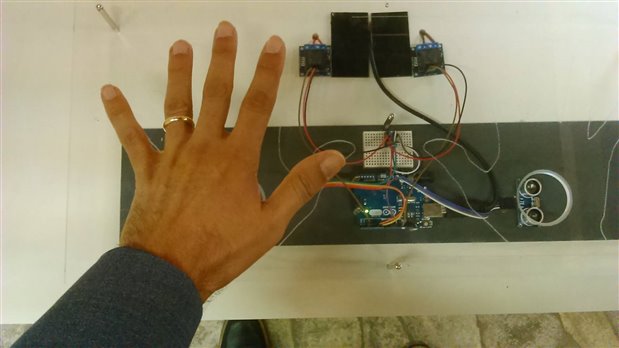
In the picture above you can see the system and how it operates (the real system we built had two sensors and two relays, each dedicated to a different device. The Arduino board can be seen in the middle. On its right there is the ultrasonic sensor. Relays can be seen on top of the figure. The sensors and the relays were covered by a transparent plexiglass screen with two holes corresponding to the position of the sensor (there is no need for the screen to be transparent: we chose it to be as such to let the users see what was inside). The holes were necessary to let the sound waves to be propagated toward the ceiling (the plexiglass screen reflects sound waves). Putting a hand close to the hole through which the sound waves pass, makes such waves to be reflected: the time needed to travel back and forth is recognised to be short enough and the corresponding relay is closed: the lamp switches on. Removing the hand the relay is opened and the lamp goes off.
Top Comments