


Table of Contents
Introduction
Sometimes, it’s nice to use a luxury display such as a VFD! This short blog post describes how to get a 12-character alphanumeric display functioning with an Arduino. It's a straightforward task - just six wires to connect!

Exploring the Display
I used this particular display; others may work too, but I don't know!:
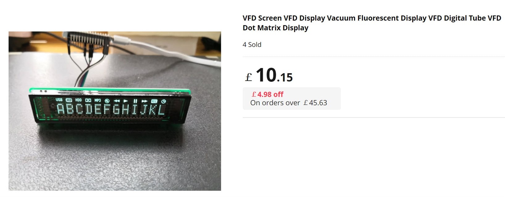
The display has six connections on the right side.
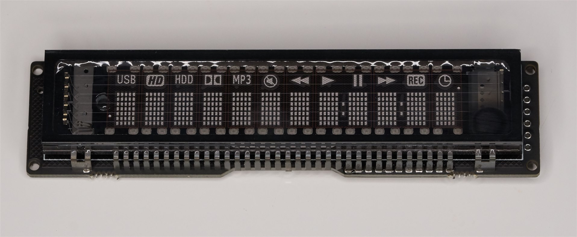
The underside of the board has not much, mainly a couple of voltage regulator integrated circuits (ICs). I don’t know what the part codes are, but connecting up a 5V supply and probing with a multimeter reveals that the left regulator provides approximately 27.8V output, and the right one generates a 3.3V output.

The in-built controller chip is part code PT6302, which I only learned through guesswork! The AliExpress product page had zero information about the display.
Connecting It Up
I’m not 100% sure, but I'm 95% sure the display requires 3.3V logic levels if I assume that the 3.3V regulator is providing the logic supply for the PT6302 chip, which is inaccessible to probe directly. Therefore, a 5V-logic Arduino (such as Arduino Uno R3) would require logic-level conversion.
I used an Arduino R4 Minima, which normally requires 5V logic levels but was modified for 3.3V capability: Modifying the Arduino Uno R4: Making it 3.3V-Friendly
There are plenty of 3.3V logic Arduino boards that could be used instead if desired, of course.
Just four digital pins are needed. The connections I used are below.
| Connection | Arduino Pin | Description |
| DIN | D2 | Data |
| CK | D4 | Clock |
| CS | D7 | *Chip Select |
| EN | D8 | Enable |
| VCC | 5V | 5V Supply |
| GND | GND | Ground |
Arduino Code
Download the Vfd12 zip file library (it is based on code I found here. I turned that code into a library and tweaked it a bit to suit the particular VFD that I was using).
In the Arduino environment, click on Sketch -> Include Library -> Add .ZIP Library and select the zip file.
Click on File -> Examples and then near the bottom of the list, you'll see Vfd12 12-character VFD Library. Click on that and select VfdTest
Example code will be displayed. Connect to your Arduino and click on the Upload button!
It should immediately display a “Hello World” message.
The code is easy to use, and mainly just a vfd.print command will be used, for instance:
vfd.print(0, “Hello There!”);
The first parameter is the start position (0-11), and the second is the text string to display.
The code is easy to modify, but if you have problems, please leave a comment below.
What Characters are Supported?
All English characters and numbers can be displayed, i.e. alphanumeric, along with various punctuation. It is possible to user-define up to eight custom characters/symbols. The definition consists of five bytes for each custom character.

The example code demonstrates how to do that in an array. I've created some commonly-used symbols, such as degrees, left- and right-pointing triangles, and so on. The ones I created are:
0: right-pointing triangle
1: left-pointing triangle
2: pause symbol
3: overscore
4: degree symbol
5: u (micro) symbol
6: ohm symbol
7: phi character
To display a custom character, the vfd.printchar command could be used, for instance, to show a degree symbol at the seventh position on the display:
vfd.printchar(6, 4);
Summary
It was a pleasant surprise that it was so easy to use a VFD. I’d never tried this before.
The display is very clear to read and supports a decent character set with the capability to have custom symbols too. Just six wires are needed to use the display with any 3.3V logic-level Arduino board. A 5V supply is needed to power the display, however. When displaying a typical message, the current consumption of the display is about 70mA at 5V. I did not measure the current with all pixels illuminated.
All code is on GitHub. Direct link to the library.
Thanks for reading!
Gear up for your next invention with Arduino! Explore our online stores for a comprehensive list of all arduino products currently available.


