If there is a date to show affection and love to that special person we have in our lives, that date is Valentine's Day. A gift that we always have in mind is to give red roses for the meaning they have, but after a few days they begin to lose their freshness and their appearance is not as beautiful as in the early days.
In this project we are going to make a rose that we will present in a box that opens to the touch or by bringing the hand closer and with a screen in which we can put the message we want to say. It is a very original gift, and the most important thing is that we will make everything ourselves with a few materials and with all the love we want to show to that special person.
We are going to make the petals of the rose with tissue paper, since it is translucent, for the sepals, the leaves and the calyx we will use a DIN-A4 sheet of normal white paper and for the stem we will use the tube of a spray bottle. For the illumination of the rose we will use a tri-color LED diode.
The project box has dimensions of 10 x 10 cm and the rose has a height of 7 cm, the remaining 3 cm are the housing of all the circuitry.
We have used a tricolor LED because, although in the project the rose is only illuminated in red, we can illuminate it in the color of the person to whom we give the box or create a sequence of colors. We have also used a ring of 12 tricolor LEDs to highlight the green color and give luminosity to the box.
To open and close the box we have used a servomotor and as push buttons, 2 capacitive sensors that we will make ourselves with only two wires and aluminum foil.
The materials needed for this project are:
1 LED Ring 5V RGB WS2812B 12-Bit 37mm
1 LED tricolor compatible
1 Nano V3.0 CH340 chip finished soldered
1 MG90S Micro Servo Motor compatible with Arduino or SG90 Micro Servo Motor 9G for RC robot helicopter airplane
3 220 ohm resistors
2 100K ohm resistors
2 22pF capacitors
1 1,3 inch OLED I2C 128 x 64 pixel display compatible with Arduino
1 MB102 Breadboard Power Supply Adapter Power Supply Module 3.3V/5V
1 Mini Breadboard 400 Pin 4 power rail for the Jumper wires
Wires
White silk paper
White plain Paper
Plastic spray bottle tuve
Aluminium paper
Clear liquid School glue
The required software is:
Arduino IDE
Adafruit_NeoPixel library
Wire library
Adafruit_GFX library
Adafruit_SSD1306 library
CapacitiveSensor library
Servo library
valentine_day_box.ino sketch
capacitive_sensor_check.ino sketch
Design and assembly of the rose
As the aim of the Blog is electronics, we are going to explain briefly how to make our flower. The template of the parts of the flower must be adapted to the size of the rose we make.
The tissue paper is very thin and difficult to handle, to make the petals, first we will make with normal paper the support to manipulate the petals of the rose (1), with 2 petals is enough for us. Then, we have to make 3 petals of tissue paper and glue them together, making sure that their bases are at the same distance (2). For the calyx, the 5 sepals (3) and 2 leaves (4), we will use normal paper, we will paint them with green marker and on the edges of the leaves we will cut small triangles and we will have our pieces of the rose.
To assemble them, first we glue the 5 sepals forming a starfish (5), leaving a 5mm hole in the center to introduce our tricolor LED, very carefully, we fold the bases of the petals inwards and glue them to the sepals (6).
For the stem of the flower (7), we will use the tube of any spray can. For the tricolor LED of the flower, we solder the wires that we have inserted inside the tube. With the LED in the stem, we introduce it through the lower hole of the rose and glue the calyx to the sepals. To close the rose through the upper hole of the rose, we make a circle with tissue paper, we glue thin strips to it, we glue it to the rose and we have already made our flower with love.

Now we have our rose assembled. For the box, we can either make it ourselves or buy one and adapt it. We have chosen to make it.
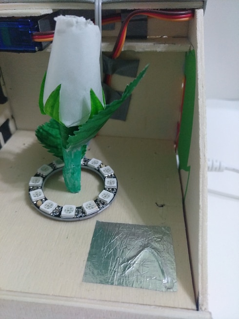
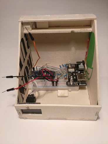
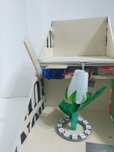
In the Mini Breadboard we will install the microcontroller, the resistors, capacitors and in our case the power supply of 5 Vdc, all this will be in the inferior part of our box. Inside the box and in sight, we will have the servo motor, the LED ring, the two capacitive sensors and inside the rose the tricolor LED diode.
Before explaining how the project works, let's explain how the capacitive sensor we will use to open and close the box works and how to make it.
Manufacturing and description of the capacitive sensor
We know that a basic capacitor is composed of 2 plates separated by a dielectric, we are going to use this principle to fabricate our capacitive sensor.
For the fabrication of our sensor, we only need a 100k ohm resistor, a 22 pF capacitor, a piece of aluminum foil and a wire.

As we can see in the circuit, we have a resistor in parallel with a capacitor and in the Receiver the piece of aluminum foil, in normal conditions, the capacitor is charged by the Sender pin up to the supply voltage, the Receiver pin takes the reading of the voltage stored in the 22 pF capacitor which remains stable. Our sensor is the piece of aluminum that will act as one of the plates of a capacitor and we as the other plate and the dielectric will be the space between us and the piece of aluminum, as we get closer the value of the dielectric will be less and we will reach a distance in which we will begin to conduct electricity, so the voltage on the Receiver pin will vary and that voltage change is the detection we need to perform any action.
To demonstrate the above we are going to make the following circuit:
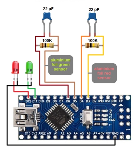
The first thing we must do is install the CapacitiveSensor library and load the capacitive_sensor_check.ino sketch, as we approach one of the pieces of aluminum foil, the corresponding led should light up. In the lines
long green_reading = green_sensor.capacitiveSensor(30);
The number in parentheses is the sensitivity of the sensor which is done by taking that number as samples in a period of time, you can change the value for the detection setting.
The scketch code is simple and each line is explained so it is very easy to follow and analyze.
Circuit and description of operation
The electronic assembly of all components is as follows:
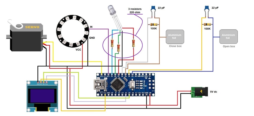
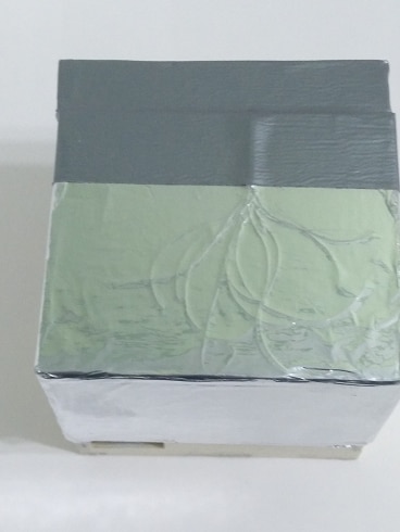
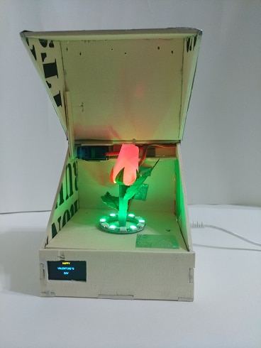
The operation is very simple, as soon as the sketch is started, the box is closed, with no light inside and the OLED display shows the message "February 14th"; When you put your hand, finger or touch (depending on the sensitivity setting) the aluminum foil on the lid, it opens with the servomotor and then the rose inside lights up red (which can also be configured in the color you want), 6 of the 12 LEDs on the ring light up green enhancing the green of the flower and the display shows the message "HAPPY VALENTINE'S DAY". Until we touch the piece of aluminum foil inside, the box does not start to close and when it does, the LED on the rose stops illuminating, the LEDs on the ring change from green to white, so that the closed box remains illuminated inside and the display returns to show the initial message "February 14".
To reopen the box we have to touch or approach again the aluminum foil of the box lid, when the box is open, the lid will not make any movement if we touch the foil of the box, because we have put a condition in the sketch, we will see it later.
Let's start analyzing the code of the sketch valentine_day_box.ino. The first thing to do is to include the necessary libraries of the modules or components that we are going to use, in the libraries are the methods that we use, for example when initializing a component or the methods to perform actions with these modules. The libraries that we include are those of the OLED screen, the I2C communication for this (Wire), the capacitive sensor, the servomotor and the WS2812B RGB LED ring.
// 1,3 inch OLED I2C 128x64 pixel display Libraries
#include <Wire.h>
#include <Adafruit_GFX.h>
#include <Adafruit_SSD1306.h>

// Library required for operation of the Capacitive Foil Sensor
#include <CapacitiveSensor.h>

// Servo Motor Library
#include <Servo.h>

// LED ring WS2812B Library
#include <Adafruit_NeoPixel.h>
After having included the libraries, we must configure the properties of each module or component and implement an object for one. The first component that we perform these actions is the LED ring. As you can see in the circuit, we have connected it to the digital pin 10 and so we reflect it in the sketch with the first line, in the second line, we indicate the number of LEDs that contains the ring that are 12.
// Define pin and number of LEDs on WS2812B ring
#define ring_LED 10
#define ring_LED_count 12
In the following line we implement an object for the ring that we call ring, in the constructor of the object we must indicate as parameters, the number of LEDs (12), the pin of the microcontroller to which we connect it (10) and the characteristics of the ring that are tricolor LEDs (RGB) and work at a frequency of 800 KHz.
// WS2812B ring object
Adafruit_NeoPixel ring(ring_LED_count, ring_LED, NEO_GRB + NEO_KHZ800);
In the following lines we configure a series of colors by means of RGB values of each LED, for example, for the red color, we must activate the red LED and leave the green and blue LEDs deactivated. For the yellow color, we activate the red and green LEDs and leave the blue one deactivated, the two light independently, but the human eye detects the mixture of the two colors.
// WS2812B ring colors
uint32_t red = ring.Color(150,0,0);
uint32_t green = ring.Color(0,150,0);
uint32_t blue = ring.Color(0,0,150);
uint32_t yellow = ring.Color(150,150,0);
uint32_t purple = ring.Color(150,0,150);
uint32_t light_blue = ring.Color(0,150,150);
uint32_t white = ring.Color(150,150,150)
The next component we configure is the OLED screen. Its characteristics are 128 pixels wide and 64 pixels high and we reflect this in the two variables in the following lines.
#define SCREEN_WIDTH 128
#define SCREEN_HEIGHT 64
To implement a display object, the constructor parameters that we must reflect are the display width and height variables, &Wire is a call to an address of the I2C communication Wire library and the -1 would be the reset pin connection, if any.
Adafruit_SSD1306 display(SCREEN_WIDTH, SCREEN_HEIGHT, &Wire, -1);
The next two rows are the implementations of two objects of the capacitive sensor class for the detection in the sensors of opening and closing the box. The first parameter is the sender pin, through which we feed 5 Vdc to the sensors and the second parameter is the receiver, through which we detect the voltage variation when we activate the sensors when we approach or touch it.
CapacitiveSensor touch_open = CapacitiveSensor(4, 3);
CapacitiveSensor touch_close = CapacitiveSensor(6, 5);
For the servomotor configuration, we first implement the object called servo_box of the Servo class and define a variable called grades to store the servomotor position value in degrees.
Servo servo_box;
int grades;
And the last 3 lines of the definition block are the pins of the microcontroller where we connect the pins of the tricolor diode for the rose, the pins are digital 7, 8 and 9 for the colors red, green and blue respectively.
#define red_LED 7
#define green_LED 8
#define blue_LED 9
The next block is the setup(), which is only executed once and is the initial configuration of the components when supplying voltage to the microcontroller and starting up. We start initializing the IDE serial console, we also initialize the OLED screen and check that it is connected through address 0x3C by I2C communication protocol, if it is not connected or the address of this was another, a message will appear in the IDE serial console communicating it.
Serial.begin(9600);
if(!display.begin(SSD1306_SWITCHCAPVCC, 0x3C)) {
      Serial.println(F("SSD1306 allocation failed"));
      for(;;);
}
Once the screen is initialized, we want to display a message for it and for that, we must give values to the parameters of the methods of the screen object. We set the color of the text, the font size (2 corresponds to a height of 16 pixels), we position the cursor in column 20 and row 0, where we want to write "February", the next thing is to place the cursor in column 40 and row 30 to write the word "14th". When we have already assigned all the values of the text properties and the text itself, with the following statement ( display.display() ) we give the command to display on the screen the text described in the previous lines with the values of positioning, font size and color.
display.clearDisplay();
display.setTextColor(WHITE);
display.setTextSize(2);
display.setCursor(20,0);
display.print("February");
display.setCursor(40,30);
display.print("14th");
display.display();
In the next line of the setup() block we indicate that we have connected the servomotor to pin 12 of the microcontroller.
servo_box.attach(12);
In this block we must also configure the pins of the microcontroller where we have connected the tricolor LED of the rose as output pins to provide us with output voltage to power the three LEDs. Recall that we had defined 3 variables with the pin numbers in the previous block.
pinMode(red_LED, OUTPUT);
pinMode(green_LED, OUTPUT);
pinMode(blue_LED, OUTPUT);
The last line of this block is the initialization of the LED ring.
ring.begin();
Now we move on to the loop() block which is the block that is continuously running. It has been simplified by methods to have a cleaner and more schematic code. In this block we only have the definitions of two variables for the values of the capacitive sensors to open and close the box and the simple conditional blocks to check the values and execute the corresponding methods. We have to remember that the number in brackets ( (30) ) in the lines of definition of the variables is the sensitivity, which performs taking that number of samples in a period of time, we must adjust it to detect presence and execute the corresponding action.
The detection is done because when we approach the aluminum foil, we "create a capacitor" between us and the box, the dielectric is the distance from the aluminum to our finger or hand and this causes the voltage value on the sender pin to change, the value is stored in the variables open_box or close_box that we declare in the same sentence and these variables are passed to the conditional if as arguments for testing and when a condition is met, the corresponding method is executed, opening_box or closing_box.
long open_box = touch_open.capacitiveSensor(30);
long close_box = touch_close.capacitiveSensor(30);

if(open_box > 1) {
        opening_box();
    }

if(close_box > 1) {
        closing_box();
    }
Let's analyze the opening_box method of our box. When this method starts executing, the first thing we program is the reading of the servomotor position, because if the box is open we would not have to perform any action, if the servomotor position is higher than 175 degrees, it means that it is open and we will return to the point from where we jump to this method, that is, to the loop() block.
grades = servo_box.read();
if (grades>175) {
   return;
}
Otherwise, if the box is closed we execute the for-counter loop and the position of the servomotor will move from the 90 degree position to 180 degrees, and then immediately illuminate our rose in red.
else {
    for (int pos=90; pos<180; pos++) {
        servo_box.write(pos);
        delay(10);
    }
}

color_LED(255, 0, 0);
The WS2812B RGB LED ring will illuminate green 6 of the 12 LEDs it contains, the methods we program to do this follow the following order, first we turn off all the LEDs if they are illuminated, we set the brightness to a value of 50 out of a total of 255, we declare the LEDs we want to use and the color of each one of them; here we must remember that they are listed from LED0 to LED11 and finally we execute everything previously declared with the sentence ring.show();.
ring.clear();
ring.setBrightness(50);
ring.setPixelColor(0, green);
ring.setPixelColor(2, green);
ring.setPixelColor(4, green);
ring.setPixelColor(6, green);
ring.setPixelColor(8, green);
ring.setPixelColor(10, green);
ring.show();
When the box is open we change the message on the screen to "HAPPY VALENTINE'S DAY", the lines of code we use are:
display.clearDisplay();
display.setTextSize(1);
display.setCursor(50,0);
display.print("HAPPY");
display.setCursor(30,20);
display.print("VALENTINE'S");
display.setCursor(55,40);
display.print("DAY");
display.display();
These lines are similar to those previously described in the setup() block, where we also displayed the text "February 14th" on the screen. With the analysis of the statements of the opening_box() method it will be very easy to perform the analysis of the closing_box() block by yourself, since they are practically similar.
The last method we have in the sketch is used to illuminate the tricolor LED of the rose, this LED is composed of 3 independent diodes, which are illuminated and by the visual mixture of the three, we can display the colors we want, the values must be RGB values up to 255.
void color_LED (int value_red_LED, int value_green_LED, int value_blue_LED)
Capacitive_sensor_check.ino
// CapacitiveSensor library necesary
#include <CapacitiveSensor.h>

CapacitiveSensor red_sensor = CapacitiveSensor(4,3);      // Create and indicate red led sensor pins 4 -> Sender 3 -> Receiver
CapacitiveSensor green_sensor = CapacitiveSensor(6,5);    // Create and indicate green led sensor pins 6 -> Sender 5 -> Receiver

void setup() {

    pinMode(12,OUTPUT);             // Pin 12 (red LED) like output
    pinMode(11,OUTPUT);             // Pin 11 (green LED) like output

}

void loop() {

    // The number in parentheses is the sensor sensitivity and can be adjusted.
    long red_reading = red_sensor.capacitiveSensor(30);        // Storing the red LED sensor reading in a variable.
    long green_reading = green_sensor.capacitiveSensor(30);    // Storing the green LED sensor reading in a variable

    //Compare readings
    if(red_reading > 1)
      digitalWrite(12,HIGH);
    else
      digitalWrite(12,LOW);

    if(green_reading > 1)
      digitalWrite(11,HIGH);
    else
      digitalWrite(11,LOW);

    delay(10);
}
Valentine_day_box.ino
/*****************************************************************************
 *  valentine_day_box                                                        *
 *  28-01-2022                                                               *
 *  Spain_mtg		                                                     *
 ****************************************************************************/

// 1,3 inch OLED I2C 128x64 pixel display Libraries
#include <Wire.h>
#include <Adafruit_GFX.h>
#include <Adafruit_SSD1306.h>

// Library required for operation of the Capacitive Foil Sensor
#include <CapacitiveSensor.h>

// Servo Motor Library
#include <Servo.h>

// LED ring WS2812B Library
#include <Adafruit_NeoPixel.h>

// Define pin and number of LEDs on WS2812B ring
#define ring_LED 10
#define ring_LED_count 12

// WS2812B ring object
Adafruit_NeoPixel ring(ring_LED_count, ring_LED, NEO_GRB + NEO_KHZ800);

// WS2812B ring colors
uint32_t red = ring.Color(150,0,0);
uint32_t green = ring.Color(0,150,0);
uint32_t blue = ring.Color(0,0,150);
uint32_t yellow = ring.Color(150,150,0);
uint32_t purple = ring.Color(150,0,150);
uint32_t light_blue = ring.Color(0,150,150);
uint32_t white = ring.Color(150,150,150);

// Implementation of a screen object
#define SCREEN_WIDTH 128
#define SCREEN_HEIGHT 64
Adafruit_SSD1306 display(SCREEN_WIDTH, SCREEN_HEIGHT, &Wire, -1);

CapacitiveSensor touch_open = CapacitiveSensor(4, 3);		// Capacitive sensor pins to open the box: pin 4 -> Sender pin 3 -> Receiver
CapacitiveSensor touch_close = CapacitiveSensor(6, 5);		// Capacitive sensor pins to close the box: pin 6 -> Sender pin 5 -> Receiver

// Implementation of a servo object and a variable for the position of the lid
// Box closed ---> servo motor position 90 degrees
// Box open ---> servo motor position 180 degrees
Servo servo_box;
int grades;

// Define pins RGB LED
#define red_LED 7
#define green_LED 8
#define blue_LED 9


void setup() {

    Serial.begin(9600);
    if(!display.begin(SSD1306_SWITCHCAPVCC, 0x3C)) {            // Display connection check
          Serial.println(F("SSD1306 allocation failed"));
          for(;;);
    }

    // Display message when initializing the sketch
    delay(10);
    display.clearDisplay();                                     // Delete screen content
    display.setTextColor(WHITE);                                // Set color text
    display.setTextSize(2);                                     // Set font size
    display.setCursor(20,0);                                    // Position the cursor in column 20 and row 0
    display.print("February");                                  // Word to be displayed
    display.setCursor(40,30);                                   // Position the cursor in column 40 and row 30
    display.print("14th");                                      // Word to be displayed
    display.display();                                          // Show all the above words with the settings

    //Pin 12 servomotor connected
    servo_box.attach(12);

    // Microcontroller pins to LED pins configuration
    pinMode(red_LED, OUTPUT);
    pinMode(green_LED, OUTPUT);
    pinMode(blue_LED, OUTPUT);

    // Initialize WS2812B ring
    ring.begin();

}

void loop() {

    long open_box = touch_open.capacitiveSensor(30);        // Variable to store the value of open box, sensitivity in parentheses

    long close_box = touch_close.capacitiveSensor(30);      // Variable to store the value of close box, sensitivity in parentheses

    // Compare readings
    if(open_box > 1) {
        opening_box();              // Call to the method of opening the box
    }

    if(close_box > 1) {
        closing_box();             // Call to the method of closing the box
    }

}


// Open box method
void opening_box() {

    // With this double conditional we avoid that if the box is open and we click on open the box, it closes and reopens again.
    grades = servo_box.read();
    if (grades>175) {                             // We check that if the servo motor position is higher than 170 degrees we exit and the lid does not move.
      return;
    } else {
      for (int pos=90; pos<180; pos++) {          // If it is lower, the box opens at slow speed up to 180 degrees.
        servo_box.write(pos);
        delay(10);
      }
    }

    // We turn on the tricolor LED to red
    color_LED(255, 0, 0);                         // Method of analog outputs to illuminate the red tricolor LED.

    ring.clear();                                 // Power off the LEDs
    ring.setBrightness(50);                       // Set Luminosity set to 50 out of 255
    ring.setPixelColor(0, green);                 // We set the LED 1 of 12 of the ring lights green
    ring.setPixelColor(2, green);                 // LED 3
    ring.setPixelColor(4, green);                 // LED 5
    ring.setPixelColor(6, green);                 // LED 7
    ring.setPixelColor(8, green);                 // LED 9
    ring.setPixelColor(10, green);                // LED 11
    ring.show();                                  // Turn on the LEDs with the configured color and brightness.

    display.clearDisplay();                       // Delete screen content
    display.setTextSize(1);                       // Set font size
    display.setCursor(50,0);                      // Position the cursor in column 50 and row 0.
    display.print("HAPPY");                       // Word to be displayed
    display.setCursor(30,20);                     // Position the cursor in column 30 and row 20.
    display.print("VALENTINE'S");                 // Word to be displayed
    display.setCursor(55,40);                     // Position the cursor in column 55 and row 40.
    display.print("DAY");                         // Word to be displayed
    display.display();                            // Show all the above words with the settings

}

// Close box method
void closing_box() {

    // With this double conditional we avoid that if the box is close and we click on close the box, it open and reclose again.
    grades = servo_box.read();
    if (grades<95) {                              // We check that if the servomotor position is less than 95 degrees we go out and the cover does not move.
      return;
    } else {
      for (int pos=180; pos>90; pos--) {          // If higher, the box closes at slow speed up to 90 degrees.
        servo_box.write(pos);
        delay(10);
      }
    }

    display.clearDisplay();                       // These lines are similar to the one described in opening the box.
    display.setTextSize(2);
    display.setCursor(20,0);
    display.print("February");
    display.setCursor(40,30);
    display.print("14th");
    display.display();

    color_LED(0, 0, 0);                           // Analog outputs method to turn off the tri-color LED.

    ring.clear();
    ring.setBrightness(50);                       // These lines are similar to those described when opening the box but change the color and number of the LEDs.
    ring.setPixelColor(1, white);
    ring.setPixelColor(3, white);
    ring.setPixelColor(5, white);
    ring.setPixelColor(7, white);
    ring.setPixelColor(9, white);
    ring.setPixelColor(11, white);
    ring.show();
}

// Method for the tricolor LED color
void color_LED (int value_red_LED, int value_green_LED, int value_blue_LED) {

      // Analog output method for the tricolor LED (output pin, RGB value)
      analogWrite(red_LED, value_red_LED);
      analogWrite(green_LED, value_green_LED);
      analogWrite(blue_LED, value_blue_LED);
}