


Master Plan: Plug a CAN-Bus MKR Shield onto Arduino 4000 and read car's OBD-II data so it could be displayed on an HDMI screen in graphical form. What could be simpler, it should only take 10 minutes to bolt together one of the many CAN-bus examples to a graphical HDMI driver. The FPGA section could be used to scroll the graphical section of the screen horizontally, at high speed, in the same manner as done on an oscilloscope. So the graphs of engine speed, mass air flow, throttle position etc would be displayed in real time. Additionally an accelerometer could be added.
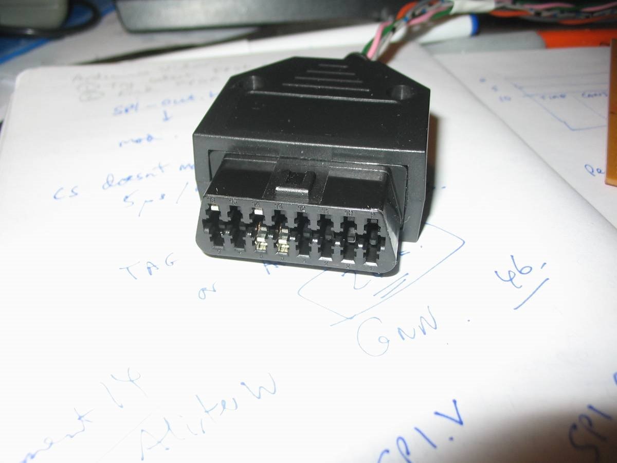
Before the Arduino Vidor 4000 arrived, I purchased an OBD-II connector and wired up its crimp terminals to what should be CAN+. CAN-, Ground and +12V.
That master plan has kind of had to be diluted as at the moment, the graphical screen resolution of the FPGA code is rather low, and besides, the Police don't take kindly to people driving with a screen visible and I don't really wish to become a star on 'Police Interceptors' trying to explain that it is not actually a DVD player. Back-up plan is now to display CAN and OBD data in text format by bolting together the TEXT-DEMO FPGA code from Giacko68 to the OBD-II Arduino code from Loovee. This time the FPGA could be used to vertically scroll a central text display window by simultaneously moving each column up a row.
TEXT-DEMO was extracted from GitHub and it ran correctly. Two warnings:
1. My micro-USB cable was a bit wobbly and caused lots of problems with intermittent contacts. If you have trouble running published Vidor stuff then do try a decent cable,
2. Have patience! The FPGA loads itself on power-up via JTAG and THIS TAKES APPROX. 30 SECONDS! You should see the red led flash three times quickly then go off while the JTAG does its stuff. Finally the red led comes on and you will get HDMI video. Don't panic if you see no video during the JTAG load!
2.5 Purely as a comment, some time ago I purchased an HDMI cable from a '99p' shop. Sadly it did not work with a Raspberry Pi. However one bought from a Pound Shop did work...took a long time to figure out why the Pi wasn't working.
First problem to solve was to regenerate the FPGA file as required by TEXT-DEMO, so it could be modified. I used Quartus-II v18.1 on a Windows 10 PC. It would build the output file but that file would not run for some weird reason. After plenty of mucking about, I installed v18.0, and that generated a functional file, so I could run the TEXT-DEMO and get an HDMI text display on my HDMI monitor. Giacko also did some tests and had no problems using v18.0 and v18.1, but the subtle difference was his O.S. was Linux. Incidentally, some of the Vidor 4000 instructions state that a patch is required for v18.0, and that is supplied as shell scripts what Windows does not seem to like at all, so I didn't add these patches. I did try to run an old 32-bit laptop with Lubuntu to get round this problem, but many tools just don't play 32-bit mode any more, so I gave up on Linux.
As an experiment, it seemed a fun idea to use the FPGA's soft SPI ports, but I couldn't get any data from the MISO pin. Besides, the 'VidorPeripheral' FPGA code is not the same as the TEXT-DEMO FPGA code so I would have probably had to cut and paste some Verilog over. But the SAMD21's SPI port fired up immediately and I could get data in and out of the MKR CAN Shield. I tried the VidorPeripheral UART code as an experiment and that did work.
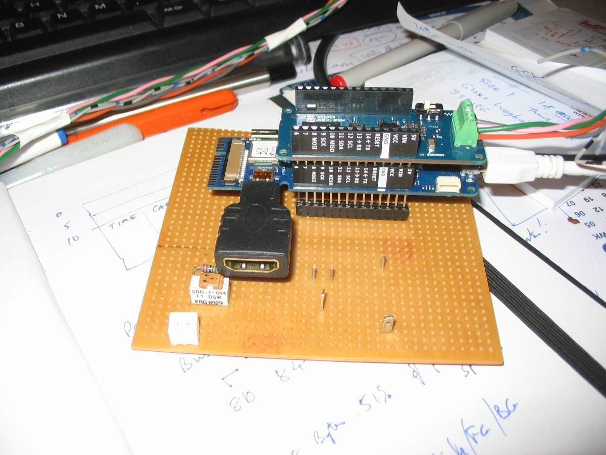
The next problem was that TEXT-DEMO now refused to display anything when the CAN Shield was plugged in. That was because both the MCP2515 CAN interface and FPGA text interface use the same SPI port and also some control lines e.g. INT and FPGA_CS (chip select) on the same pin. Because the Shield is hard-wired I had to move the FPGA_CS signal from Pin 7, to Pin 6, and that was very easy to do: in the Pin Assignment editor, change SPI_CS's pin from F16 to G16. The SPI port can talk to multiple devices provided chip selects are separated. To make debug easier, I soldered a 28-pin IC socket onto a piece of strip board and soldered in some pins on useful tracks viz. 0V, MISO, MOSI, SCLK and Pin 3 (CAN_CS). The switch was from a previous project! An HDMI converter is plugged in.
Then I rebuilt the FPGA project. Copy the .SVF file from output_files up a couple of directory levels to where MakeImage.py lives. This python file can be run from the Command Prompt. I use Python 3.7.1 by the way.
The Python warnings about not being able to find the path specified may be ignored as they expect a Linux command line. I have slightly modified this program; as an aside, Python is a very useful language and can run fancy graphics and games, with upside-down text if you like(!) on both Windows/Linux, but sadly keyboard input is not so compatible. It takes about 30 seconds for this Python program to run. Patience! End result is an RLE-encoded header file FLGA_Image_RLE.h which the Arduino code loads into the FPGA.
Changing the Arduino program to use CS on pin 6 was easy as adding
const int SPI_FPGA_CS_PIN = 6; to TEXT.ino.
Next interesting problem to solve was running two slaves from one master SPI module in the SAMD21. The FPGA uses an active high chip select, whereas the MCP2515 is active low. MKR pin 3 is hard-wired as the MCP2515 CS pin, so uses:
const int SPI_CAN_CS_PIN = 3;
The chip select signal have to be set or reset before SPI transactions, so I have made some minor changes to do this. I then used an MSO to ensure that the two chip selects were never active at the same time, and the results looked good as there were no obvious occasions where both chip selects were active.
Sunday 27th Jan, and one day before the deadline of 28th Jan. Bit of partying last night until 2am and there is some more work to do:
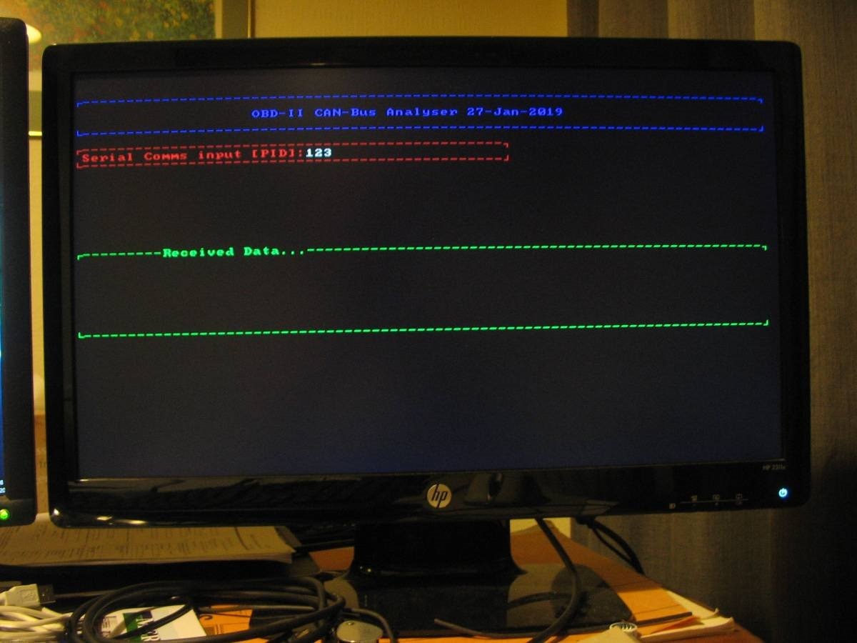
Set up some rectangular panels on the display to hold text messages (title, keyboard command entry, received CAN message display and possibly their meaning), modify the Verilog code to scroll one of the panels, add the scroll command to the Arduino software, and test it. The TEXT-DEMO uses an ASCII character set containing some simple graphic shapes that can be used to draw lines to define each panel. This technique was used in the days of DOS, and Teletext before pixels could be individually set.
I have not learnt Verilog, or C++ for that matter, but I have used programmable logic devices before. Altera's EP300 was my first venture if I remember correctly, and used various tools such as PALASM and schematic entry. Another device we used was Philip's Coolrunner. But FPGAs don't seem to like PALASM and even though I recently tried schematic entry of a couple of NAND gates on a Cyclone II, that didn't work.
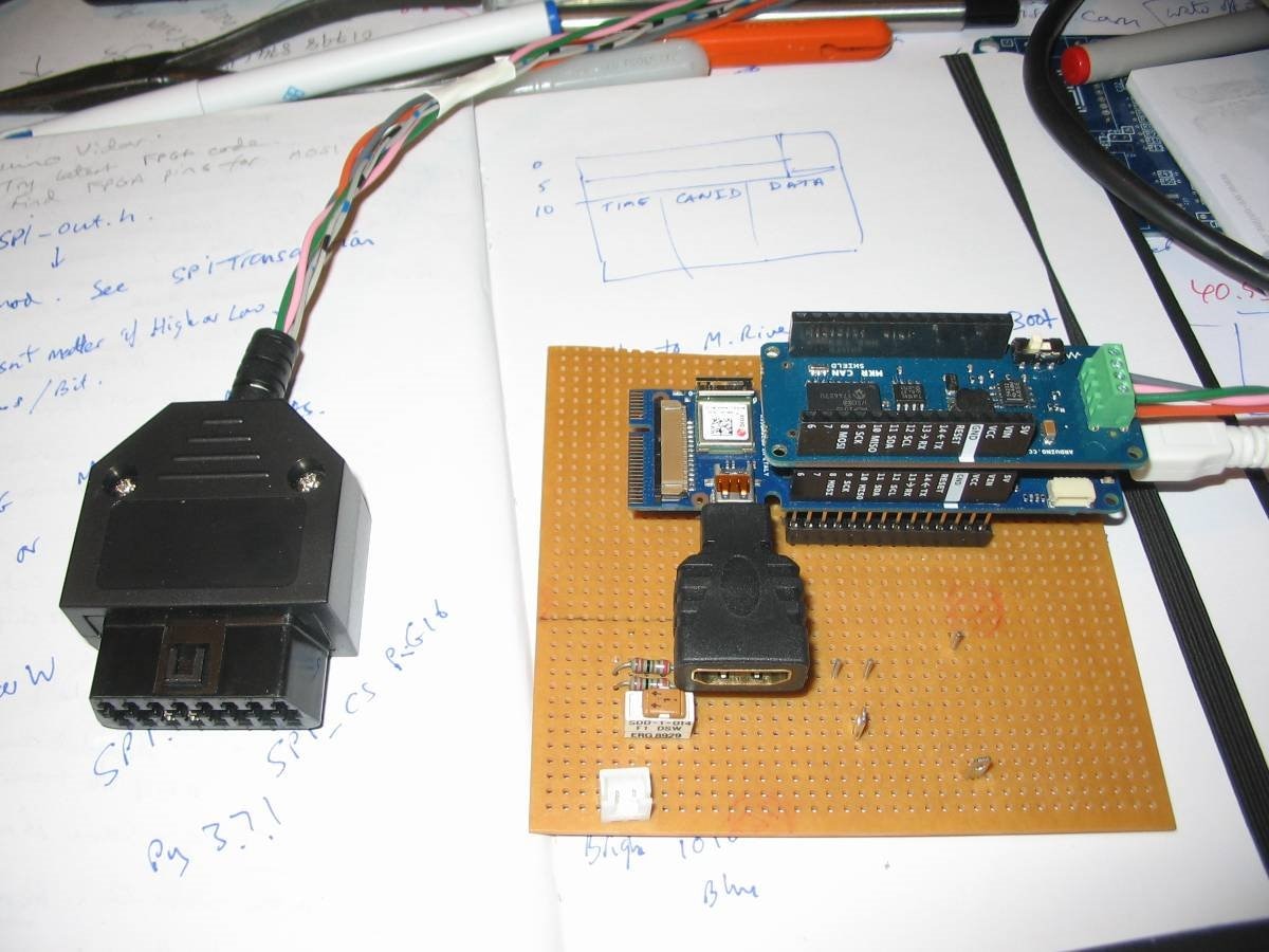
Due to not understanding enough Verilog, I did not manage to do the scroll in FPGA, but had to use the SAMD21 for that. Maybe I will get an idle moment and revisit it. I will also revisit the JTAG loading and see if it can be speeded up. Here is a view of the board ready to be plugged in the car...
And here is the test-based screen display:
It was a bit wet and windy this afternoon as I tried to install the Arduino etc and monitor in my car. That is when a slight nooby problem came along...eagle-eyed readers will have noticed that the sex of my connector is wrong! It would not plug into the female connector on the car! So I will have to order a male connector before I can test it.
Top Comments