element14 Community
element14 Community
    Register Log In
  • Site
  • Search
  • Log In Register
  • About Us
  • Community Hub
    Community Hub
    • What's New on element14
    • Feedback and Support
    • Benefits of Membership
    • Personal Blogs
    • Members Area
    • Achievement Levels
  • Learn
    Learn
    • Ask an Expert
    • eBooks
    • element14 presents
    • Learning Center
    • Tech Spotlight
    • STEM Academy
    • Webinars, Training and Events
    • Learning Groups
  • Technologies
    Technologies
    • 3D Printing
    • FPGA
    • Industrial Automation
    • Internet of Things
    • Power & Energy
    • Sensors
    • Technology Groups
  • Challenges & Projects
    Challenges & Projects
    • Design Challenges
    • element14 presents Projects
    • Project14
    • Arduino Projects
    • Raspberry Pi Projects
    • Project Groups
  • Products
    Products
    • Arduino
    • Avnet Boards Community
    • Dev Tools
    • Manufacturers
    • Multicomp Pro
    • Product Groups
    • Raspberry Pi
    • RoadTests & Reviews
  • Store
    Store
    • Visit Your Store
    • Choose another store...
      • Europe
      •  Austria (German)
      •  Belgium (Dutch, French)
      •  Bulgaria (Bulgarian)
      •  Czech Republic (Czech)
      •  Denmark (Danish)
      •  Estonia (Estonian)
      •  Finland (Finnish)
      •  France (French)
      •  Germany (German)
      •  Hungary (Hungarian)
      •  Ireland
      •  Israel
      •  Italy (Italian)
      •  Latvia (Latvian)
      •  
      •  Lithuania (Lithuanian)
      •  Netherlands (Dutch)
      •  Norway (Norwegian)
      •  Poland (Polish)
      •  Portugal (Portuguese)
      •  Romania (Romanian)
      •  Russia (Russian)
      •  Slovakia (Slovak)
      •  Slovenia (Slovenian)
      •  Spain (Spanish)
      •  Sweden (Swedish)
      •  Switzerland(German, French)
      •  Turkey (Turkish)
      •  United Kingdom
      • Asia Pacific
      •  Australia
      •  China
      •  Hong Kong
      •  India
      •  Korea (Korean)
      •  Malaysia
      •  New Zealand
      •  Philippines
      •  Singapore
      •  Taiwan
      •  Thailand (Thai)
      • Americas
      •  Brazil (Portuguese)
      •  Canada
      •  Mexico (Spanish)
      •  United States
      Can't find the country/region you're looking for? Visit our export site or find a local distributor.
  • Translate
  • Profile
  • Settings
Arduino Projects
  • Products
  • Arduino
  • Arduino Projects
  • More
  • Cancel
Arduino Projects
Blog Week 1:  Making it Portable
  • Blog
  • Documents
  • Events
  • Polls
  • Files
  • Members
  • Mentions
  • Sub-Groups
  • Tags
  • More
  • Cancel
  • New
Join Arduino Projects to participate - click to join for free!
  • Share
  • More
  • Cancel
Group Actions
  • Group RSS
  • More
  • Cancel
Engagement
  • Author Author: fmilburn
  • Date Created: 6 Dec 2018 4:59 AM Date Created
  • Views 2414 views
  • Likes 12 likes
  • Comments 5 comments
  • mkr relay shield
  • buoy
  • mkr_giveaway_projects
  • lorawan
  • arduino_projects
  • lora
  • arduino mkr 1300
  • boat
  • icp-10100
  • arduino
  • mkr_smarterworld
  • wan_1300
Related
Recommended

Week 1:  Making it Portable

fmilburn
fmilburn
6 Dec 2018
image

Arduino Home

An Open-Source platform to create digital devices and interactive objects that sense and control physical devices.

Arduino Tutorials
Arduino Projects


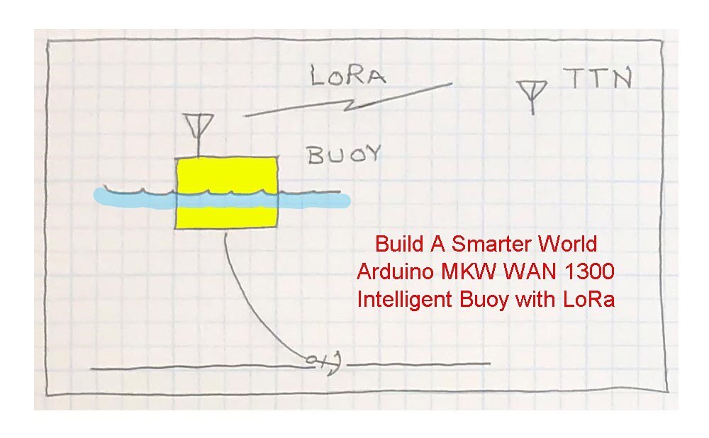
I am prototyping a an Intelligent Buoy (that evolved into a boat) that uses LoRa to communicate with a base station using the Arduino MKR WAN 1300.  This post covers making a more robust prototype board for field testing and the issues encountered.

image

Daughter Board

All work up until now has been on breadboards and it is time to make something sturdier that can be used in the field.  For now, only an Invensys ICP-10100 Barometric Pressure and Temperature Sensor is hooked up to the Arduino Relay Shield.

image

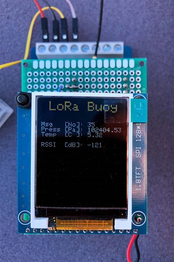
The video below outlines a daughter board which features a 120 x 160 TFT screen as well as some real estate to hook up sensors in the future.  The TFT screen will be used primarily for debugging and testing prior to deployment and is easily removed when desired.

You don't have permission to edit metadata of this video.
Edit media
x
image
Upload Preview
image

Firmware

An incomplete outline of the code is shown below...

#include <MKRWAN.h>
#include "ArduinoLowPower.h"
#include <Adafruit_GFX.h>   
#include <Adafruit_ST7735.h>
#include <SPI.h>
#include <LoRa.h>
#include <icp101xx.h>

struct data{
  unsigned long numMeasures;
  float pressPa;
  float tempC;
} readings;

const unsigned long SLEEP_TIME  = 5000;      
const unsigned long LISTEN_TIME = 200;

void setup(void) {
  initGPIO();
  splashScreen();
  initLoRa();
  initPressure();
}

void loop() {
    getReadings(readings);
    sendLoRa(readings);
    listenLoRa();
    
    delay(SLEEP_TIME);
}

To add a new sensor it is necessary to:

  • #include the appropriate library
  • add values to the data struct which store the sensor readings
  • add an initializing function in setup()
  • add a reading function in getReadings()
  • add print statement(s) for the values in sendLoRa()


The function listenLoRa() waits a short period to see if the base station returns a command.  For now, it just returns RSSI.  Note the delay(SLEEP_TIME) function call at the bottom of the loop.  I tried using LowPower.deepSleep(SLEEP_TIME) which is in the low power library for the Arduino SAMD21 but need to address these two concerns:

  1. The loop executes quite quickly and then in my code sleeps for 5 seconds.  While sleeping the USB port closes on my Windows 10 computer and then the Arduino IDE cannot flash updates when modifying the code.  I finally overcame this by holding the reset button on the MKR WAN 1300 until just before the IDE began the flash and releasing it which works as a somewhat hit and miss kludge but I find it disconcerting and for now am using delay().
  2. Even in deep sleep the MKR WAN 1300 draws more than 1 mA according to posts on the Arduino forum.  I have not tested this on my board yet but plan to do so in the coming week.

I would be interested if others are seeing these problems and how they address them.


Field Tests

There is a view of the Puget Sound from the deck at the back of my house and the plan is to test the buoy first from a little public beach beside the ferry dock.  It is clear most of the way with some trees and an embankment partially blocking.

image

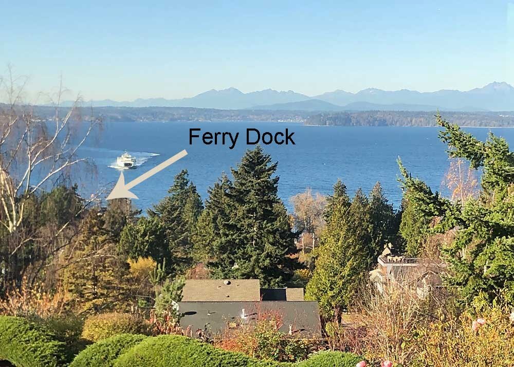
The beach is about a kilometer away as the crow flies.  The MKR WAN 1300 serving as the base unit was hoisted up on a pole and clamped to the house to get the antenna as high as possible and give the clearest view.

image

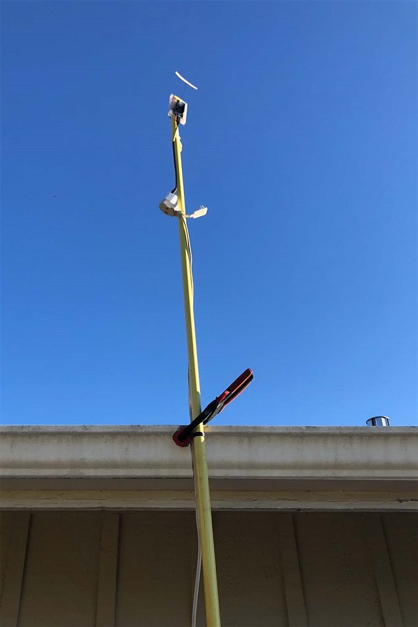
It looks like I need to scrub the gutter :-).  Then I took my battery powered buoy unit down to the beach and leaned it against a log to see what the reception is like.

image

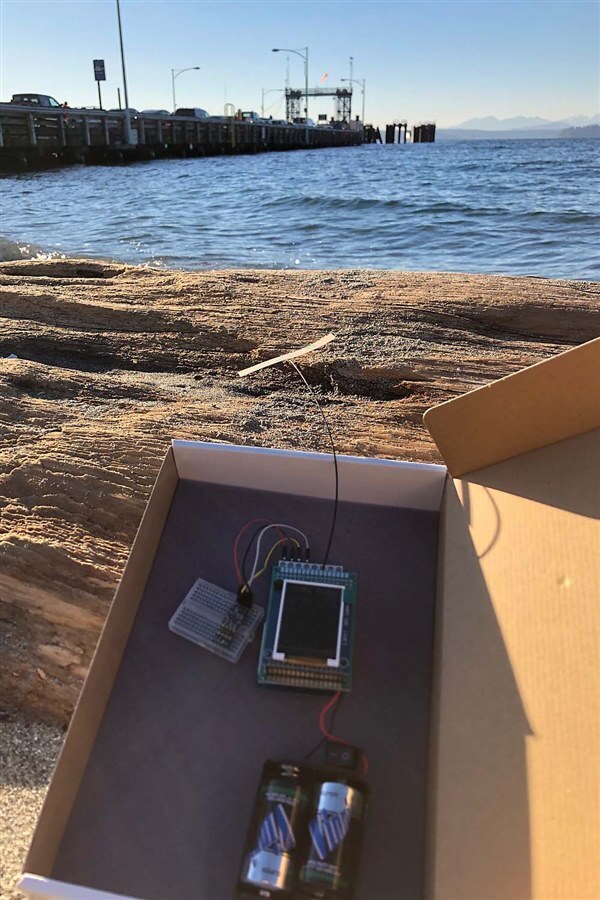
The limit seems to be around -122 for reliable reception.

image

Moving my body in front of the antenna was enough to cut off reception.  If I lifted it up to waist height and pointed the antenna towards the house the reception improves to around -118 or so.  I conclude that I can probably do some testing in the area below my house but it is less than ideal.  Maybe a directional antenna for the base station?

I plan to hold off publishing schematics and full code listings until further in development but if something interests you just ask and I will shoot it your way.  The landing page for all the posts in this project is the first link given below.  Comments, corrections, and ideas are always welcome!

Links

MKR WAN 1300: LoRa Marine Environmental Ranger

Winners Announcement: Build a Smarter World: Build an Arduino MKR WAN 1300 Project for an Arduino Engineering Kit!

  • Sign in to reply

Top Comments

  • jc2048
    jc2048 over 6 years ago +3
    I'm not an expert in rf stuff, so get a second opinion on anything I say here, but... Wouldn't it be better with the dipole vertical? I think the radiation pattern has the highest energy coming off perpendicular…
  • jc2048
    jc2048 over 6 years ago in reply to fmilburn +3
    That looks more complicated than I was expecting. It is still essentially a dipole, even if folded up a bit and not fed the way you would with a pair of elements. The hot feed (the inner of the coax) goes…
  • genebren
    genebren over 6 years ago +2
    Nice work on your project. It was good that you decided to test the communications link before moving further into the project. Hopefully you can figure out a antenna configuration that will improve your…
  • jc2048
    jc2048 over 6 years ago in reply to fmilburn

    That looks more complicated than I was expecting. It is still essentially a dipole, even if folded up a bit and not fed the way you would with a pair of elements. The hot feed (the inner of the coax) goes across to a coil and then right to a capacitor to couple it on to the right arm of the dipole. Presumably, that's to get the matching to the antenna to look like 50 ohms.


    The folds (the zig-zag stretch and bringing it around at the ends) give some radiation off in the direction of the left-right axis of your photo where there would otherwise be a null and make it a bit more omnidirectional. Unfortunately, there doesn't seem to be a plot of the radiation pattern in their data.


    This probably calls into question my suggestion of a reflector at the house end. The reflector needs to be a set distance back but that gets a bit complicated if the dipole is folded up.


    Anyway, it's all interesting stuff for you to experiment with.

    • Cancel
    • Vote Up +3 Vote Down
    • Sign in to reply
    • More
    • Cancel
  • fmilburn
    fmilburn over 6 years ago in reply to jc2048

    Hi Jon and thanks for your comments.  I am sure you are right on placing the dipole vertical.  I had trouble getting the radio and antenna up at the house when the photo was taken and knowing it was horizontal also held the buoy antenna horizontal at the beach.  Poor excuse, but when I repeated the tests yesterday I was able to get everything vertical which is probably part of the reason I got better signal strength as reported in the latest blog.


    I am going to have trouble with the ground effect on the prototype as currently envisioned as the antenna will not be very high.  Also, interesting observation about rough seas.  I understand the issues now and will be on the lookout for them.  Will be giving it more thought....


    This is a closeup of the antenna I am using:

    image

    The link to the datasheet is here.  The initial reason for ordering these was the low price but I have also found these and will look at trying them next.  Also, will look into your antenna reflector suggestion..

    • Cancel
    • Vote Up +2 Vote Down
    • Sign in to reply
    • More
    • Cancel
  • jc2048
    jc2048 over 6 years ago

    I'm not an expert in rf stuff, so get a second opinion on anything I say here, but...


    Wouldn't it be better with the dipole vertical? I think the radiation pattern has the highest energy coming off perpendicular to the elements and tapering off as you move round to being on-axis - there's a null along the axis itself. As it stands, at the buoy end of the link you'd lose contact as soon as it turns through 90 degrees and the signal would be quite variable generally as it swung back and forth.


    Other things to maybe think about:


    There's a 'ground effect' with antennas in that if power is launched horizontally close to the ground then there's some absorbtion by the ground - at the bouy end that's an approximation to what's happening [basically, some of the photons that make up the radio waves will be able to 'see' the free electrons in the ground and give up energy to them]. I think you're meant to try and get the antenna at least several wavelengths above the ground and preferably more. (At 900MHz that probably just means a minimum of a metre or so, though the more height the better.)


    When the sea is calm and the surface is flat you'll get a strong reflected wave which will interfere with the direct wave. I'm not sure if there's anything you can do about that, but be aware in your testing that rough conditions may not be the worst case. [To complicate things, that interference can be constructive as well as destructive.]


    That dipole looks short to me for 900MHz. Is it foil on a plastic substrate? If so, you might get slightly better performance from a metal rod dipole. If it's shorter than you'd expect, then the substrate is a mild dielectric (slowing the wave velocity, which is why it can be shorter [good in a confined space], but also absorbing some of the energy [less good if you want the best range]). However, if the transmitter has only been certified with that antenna, then you're probably stuck with it.


    If the house antenna only needs to see the area in front of it, then there might be some benefit in putting a reflector behind it to push more of the energy forwards. (The antenna would then look like an 'H'.)

    • Cancel
    • Vote Up +3 Vote Down
    • Sign in to reply
    • More
    • Cancel
  • fmilburn
    fmilburn over 6 years ago in reply to genebren

    I had not thought about a repeater but I still plan to look at the TTN WAN again.  My daughter used to live about half way between me and the beach and that would have been perfect but they have moved.


    Frank

    • Cancel
    • Vote Up 0 Vote Down
    • Sign in to reply
    • More
    • Cancel
  • genebren
    genebren over 6 years ago

    Nice work on your project.  It was good that you decided to test the communications link before moving further into the project.  Hopefully you can figure out a antenna configuration that will improve your link.  You might also be able to use a repeater of some sort to hop between the units.


    Good work and good luck!

    Gene

    • Cancel
    • Vote Up +2 Vote Down
    • Sign in to reply
    • More
    • Cancel
element14 Community

element14 is the first online community specifically for engineers. Connect with your peers and get expert answers to your questions.

  • Members
  • Learn
  • Technologies
  • Challenges & Projects
  • Products
  • Store
  • About Us
  • Feedback & Support
  • FAQs
  • Terms of Use
  • Privacy Policy
  • Legal and Copyright Notices
  • Sitemap
  • Cookies

An Avnet Company © 2025 Premier Farnell Limited. All Rights Reserved.

Premier Farnell Ltd, registered in England and Wales (no 00876412), registered office: Farnell House, Forge Lane, Leeds LS12 2NE.

ICP 备案号 10220084.

Follow element14

  • X
  • Facebook
  • linkedin
  • YouTube