


My entry for the Internet of Holiday Lights is an electro-mechanical wreath.
My first blog post was a brain dump of possibilities.
In my second post I made a paper prototype.
My third post was about getting the Arduino Yun up and running.
In the fourth post I used the Linux part of the Yun to get at the current date and time.
In the fifth post I scavenged a stepper motor from a flatbed scanner.
In post six I got that motor working using a Velleman motor driver.
I am now adding the Infineon LED shield to the design. That finishes off the electronics part of my design.
Theft
I blatantly stole Robert Peter Oakes BYOB Party #3, Infineon Library Available. I've seen in the comments on the Internet of Holiday Lights blogs that I won't be the only one running away with it. Works perfectly, Peter!
So I won't elaborate on the software part here. Check Peter's blog post.
I didn't have stacking headers available. And normal mail headers do not leave enough spece between the shields. Using them would very likely create short circuits or other mishaps.
I decided to take another approach. I soldered female headers upside down on the bottom side of the Infineon shield, and used prepped' male headers to match the female headers of the two chields.
'Prepped' means that I forced the plastic part of the male headers to the center of the pins, so that there's enough pin left on both sides to make contacts with the female headers:


Electronics prototyping finished
Now that I have all parts of the software solution tried out (I also tested the IoT MQTT library and got that working though I didn't blog about that [yet?]), I'm done with the investigating cycle.
The four main electronics functions of my design are covered:
- I can drive a motor with sufficient precision, needed to get the light filter in the correct position.
- I can talk to the linux part to get the current date for my timezone. I need that to know where I am in the advent cycle.
- I can drive the Infineon shield to handle the lights part
- I'm able to use the Eclipse IoT services for surprise functionality that I'm not going to reveal yet.
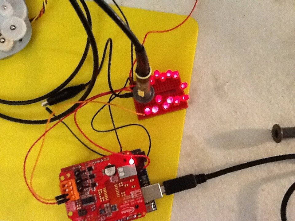
I've also tested the two most hardware dependent parts in combination: the stepper motor shield and the Infineon RGB driver shield. That worked out ok.
Here's the code of a combined stepper/led exercise:
// led shield includes
#include <Wire.h>
#include "Infineon.h"
// stepper shield includes
#include <Stepper.h>


// stepper constants
#define STEPA 4
#define STEPB 12
#define ENAA 5
#define ENAB 10
const int stepsPerRevolution = 96;

Infineon RGBLEDS = Infineon();


Stepper myStepper(stepsPerRevolution, STEPA, STEPB);


void setup() {


    Serial.begin(9600);


    // led shield
    Wire.begin();
    Serial.println("buy time to start the serial monitor...");
    delay(5000); // wait 5s
    Serial.println("polling led shield...");
    while (RGBLEDS.on != 1) // Wait for shield to respond, keep setting the values till it does
    {

      Serial.println("led shield setup");


      RGBLEDS.I2CWRITE2BYTES (ADDRESS, FADERATE, 0x0000); // Immediate fade
      Serial.println("faderate set up");
      RGBLEDS.I2CWRITE2BYTES (ADDRESS, DIMMINGLEVEL, 0x0000); // 0% brightness level
      RGBLEDS.on = RGBLEDS.I2CREAD(ADDRESS, READ_DIMMINGLEVEL); // Request for brightness level
      if (RGBLEDS.message == 1 && RGBLEDS.on == 0) // If message received and dimming level = 0%, "message" is set in the I2CREAD function
      {
        Serial.println("message check for 0");
        RGBLEDS.message = 0;
        RGBLEDS.on = 1; // break out of loop
      }
    }
    RGBLEDS.I2CWRITE2BYTES (ADDRESS, OFFTIME_RED, 0x38); // Set off-time of red channel to 0x38
    RGBLEDS.I2CWRITE2BYTES (ADDRESS, OFFTIME_GREEN, 0x38); // Set off-time of green channel to 0x39
    RGBLEDS.I2CWRITE2BYTES (ADDRESS, OFFTIME_BLUE, 0x38); // Set off-time of blue channel to 0x38
    RGBLEDS.I2CWRITE6BYTES (ADDRESS, CURRENT_RGB, 0x80, 0x05, 0x05); // max:  0x80 = 780mA
    RGBLEDS.I2CWRITE2BYTES (ADDRESS, FADERATE, 0x0000); // Fade Rate between intensities --> 0.0s
    RGBLEDS.I2CWRITE2BYTES (ADDRESS, WALKTIME, 0x0000); // walk time between colors = 0s
    RGBLEDS.I2CWRITE6BYTES (ADDRESS, INTENSITY_RGB, 0x0555, 0x0555, 0x0555); // low level White Light
    RGBLEDS.I2CWRITE2BYTES (ADDRESS, DIMMINGLEVEL, 0x0FFF); // Maximum dimming level means inensity settings are directly used

    // stepper shield
  pinMode(ENAA, OUTPUT);  //Set control pins to be outputs
  pinMode(ENAB, OUTPUT);
  digitalWrite(ENAA, LOW);
  digitalWrite(ENAB, LOW);
  // set the speed at 30 rpm:
  myStepper.setSpeed(30);


}

  // the loop routine runs over and over again forever:
  void loop() {
    Serial.println("colour loop...");
    // change lamp colour to red
    RGBLEDS.I2CWRITE6BYTES(ADDRESS, INTENSITY_RGB, 0x0, 0x0, 0x0); // all off
    delay(500); // wait 1000ms
    step(stepsPerRevolution);
    // change lamp colour to green
    RGBLEDS.I2CWRITE6BYTES(ADDRESS, INTENSITY_RGB, 0x03ff, 0x03FF, 0x03FF); // 25%
    delay(500);
    step(-stepsPerRevolution);
    // change lamp colour to blue
    RGBLEDS.I2CWRITE6BYTES(ADDRESS, INTENSITY_RGB, 0x07ff, 0x07ff, 0x07ff); // Blue
    delay(500);
    step(stepsPerRevolution);
    RGBLEDS.I2CWRITE6BYTES(ADDRESS, INTENSITY_RGB, 0x0bff, 0x0bff, 0x0bff); // Blue
    delay(500);
    step(-stepsPerRevolution);
    RGBLEDS.I2CWRITE6BYTES(ADDRESS, INTENSITY_RGB, 0x0fff, 0x0fff, 0x0fff); // Blue
    delay(500);
    step(stepsPerRevolution);
  // White, Silver, Gray, Black, Red, Maroon, Yellow, Olive, Lime, Green, Aqua, Teal, Blue, Navy, Fuchsia, Purple
    RGBLEDS.SETCOLOUR( White);
    delay(500);
    step(-stepsPerRevolution);
    RGBLEDS.SETCOLOUR(Silver );
    delay(500);
    step(stepsPerRevolution);
    RGBLEDS.SETCOLOUR(Gray );
    delay(500);
    step(-stepsPerRevolution);
    RGBLEDS.SETCOLOUR(Black );
    delay(500);
    step(stepsPerRevolution);
    RGBLEDS.SETCOLOUR(Red );
    delay(500);
    step(-stepsPerRevolution);
    RGBLEDS.SETCOLOUR(Maroon );
    delay(500);
    step(stepsPerRevolution);
    RGBLEDS.SETCOLOUR(Yellow );
    delay(500);
    step(-stepsPerRevolution);
    RGBLEDS.SETCOLOUR(Olive );
    delay(500);
    step(stepsPerRevolution);
    RGBLEDS.SETCOLOUR(Lime );
    delay(500);
    step(-stepsPerRevolution);
    RGBLEDS.SETCOLOUR(Green );
    delay(500);
    step(stepsPerRevolution);
    RGBLEDS.SETCOLOUR(Aqua );
    delay(500);
    step(-stepsPerRevolution);
    RGBLEDS.SETCOLOUR( Teal);
    delay(500);
    step(stepsPerRevolution);
    RGBLEDS.SETCOLOUR(Blue );
    delay(500);
    step(-stepsPerRevolution);
    RGBLEDS.SETCOLOUR(Navy );
    delay(500);
    step(stepsPerRevolution);
    RGBLEDS.SETCOLOUR(Fuchsia );
    delay(500);
    step(-stepsPerRevolution);
    RGBLEDS.SETCOLOUR(Purple );
    delay(500);
    step(stepsPerRevolution);

  }


void step(int steps) {
    digitalWrite(ENAA, HIGH);
    digitalWrite(ENAB, HIGH);
    myStepper.step(steps);
    digitalWrite(ENAA, LOW);
    digitalWrite(ENAB, LOW);
  }
