element14 Community
element14 Community
    Register Log In
  • Site
  • Search
  • Log In Register
  • About Us
  • Community Hub
    Community Hub
    • What's New on element14
    • Feedback and Support
    • Benefits of Membership
    • Personal Blogs
    • Members Area
    • Achievement Levels
  • Learn
    Learn
    • Ask an Expert
    • eBooks
    • element14 presents
    • Learning Center
    • Tech Spotlight
    • STEM Academy
    • Webinars, Training and Events
    • Learning Groups
  • Technologies
    Technologies
    • 3D Printing
    • FPGA
    • Industrial Automation
    • Internet of Things
    • Power & Energy
    • Sensors
    • Technology Groups
  • Challenges & Projects
    Challenges & Projects
    • Design Challenges
    • element14 presents Projects
    • Project14
    • Arduino Projects
    • Raspberry Pi Projects
    • Project Groups
  • Products
    Products
    • Arduino
    • Avnet Boards Community
    • Dev Tools
    • Manufacturers
    • Multicomp Pro
    • Product Groups
    • Raspberry Pi
    • RoadTests & Reviews
  • Store
    Store
    • Visit Your Store
    • Choose another store...
      • Europe
      •  Austria (German)
      •  Belgium (Dutch, French)
      •  Bulgaria (Bulgarian)
      •  Czech Republic (Czech)
      •  Denmark (Danish)
      •  Estonia (Estonian)
      •  Finland (Finnish)
      •  France (French)
      •  Germany (German)
      •  Hungary (Hungarian)
      •  Ireland
      •  Israel
      •  Italy (Italian)
      •  Latvia (Latvian)
      •  
      •  Lithuania (Lithuanian)
      •  Netherlands (Dutch)
      •  Norway (Norwegian)
      •  Poland (Polish)
      •  Portugal (Portuguese)
      •  Romania (Romanian)
      •  Russia (Russian)
      •  Slovakia (Slovak)
      •  Slovenia (Slovenian)
      •  Spain (Spanish)
      •  Sweden (Swedish)
      •  Switzerland(German, French)
      •  Turkey (Turkish)
      •  United Kingdom
      • Asia Pacific
      •  Australia
      •  China
      •  Hong Kong
      •  India
      •  Korea (Korean)
      •  Malaysia
      •  New Zealand
      •  Philippines
      •  Singapore
      •  Taiwan
      •  Thailand (Thai)
      • Americas
      •  Brazil (Portuguese)
      •  Canada
      •  Mexico (Spanish)
      •  United States
      Can't find the country/region you're looking for? Visit our export site or find a local distributor.
  • Translate
  • Profile
  • Settings
Arduino
  • Products
  • More
Arduino
Arduino Forum Reading UART Rx Buffer (MKR WiFi 1010 / MKR 1000)
  • Blog
  • Forum
  • Documents
  • Quiz
  • Events
  • Polls
  • Files
  • Members
  • Mentions
  • Sub-Groups
  • Tags
  • More
  • Cancel
  • New
Join Arduino to participate - click to join for free!
Actions
  • Share
  • More
  • Cancel
Forum Thread Details
  • Replies 16 replies
  • Subscribers 389 subscribers
  • Views 2814 views
  • Users 0 members are here
  • rx
  • uart
  • arduino
Related

Reading UART Rx Buffer (MKR WiFi 1010 / MKR 1000)

kas.lewis
kas.lewis over 5 years ago

Hello All,


I'm looking to create my own UART interrupt. For those who need to know why it's because I need to stop the timer as soon as a value comes in. While I know I will get a lot of reasons and explanations why this is not necessary I'm a lot more interested in how to go about doing this.


I have to commented out


void SERCOM5_Handler()

{

  Serial1.IrqHandler();

}


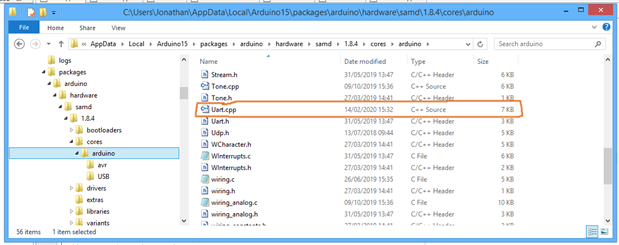
in the variant.cpp file which works to remove the Arduino code from doing what it wants. The issue I'm having now is finding the function Serial.read(). I'm trying to read the uart rx buffer but with Atmel's documentation what it is this is not as easy as it should be.


I have tried


void SERCOM5_Handler()

{

  char temp = SERCOM5->USART.DATA.reg;

  if (temp == 'h' || temp == 'H'){

    digitalWrite(LED_BUILTIN, HIGH);

  }

  if (temp == 'l' || temp == 'L'){

    digitalWrite(LED_BUILTIN, LOW);

  }

}


without much success. Therefore any help in reading the UART rx register would be very much appreciated.


Kas

  • Sign in to reply
  • Cancel

Top Replies

  • BigG
    BigG over 5 years ago +1
    I can see where you are coming from. Usually you could use the "serialEvent()" function but I see that this is not possible with Arduino SAMD Boards. Unortunately, I have no idea why but will be following…
  • michaelkellett
    michaelkellett over 5 years ago +1
    Is (temp == 'h'||temp == 'H') the same as ((temp == 'h')||(temp == 'H')) ? (brackets are free and make code easier to follow, (actually == has precedence over || in C )) How are you debugging this - can…
  • kas.lewis
    kas.lewis over 5 years ago in reply to michaelkellett +1
    Hello michaelkellett I didn't know you can put breakpoints in the Arduino IDE. Truth is there is lots about Arduino I don't know as I usually do bare metal with direct control of al registers and I also…
Parents
  • kas.lewis
    kas.lewis over 5 years ago

    Hello All, (michaelkellett)


    I think I may have made some progress... It doesn't really help having spent so long with C and left my C++ behind image although I guess this is also found in C.


    Have have found some code that may point me in the right direction but pointers and references...


    In \AppData\Local\Arduino15\packages\arduino\hardware\samd\1.8.4\variants\mkrwifi1010\variant.cpp

    Uart Serial1(&sercom5, PIN_SERIAL1_RX, PIN_SERIAL1_TX, PAD_SERIAL1_RX, PAD_SERIAL1_TX);


    In \AppData\Local\Arduino15\packages\arduino\hardware\samd\1.8.4\cores\arduino\Uart.cpp

    Uart::Uart(SERCOM *_s, uint8_t _pinRX, uint8_t _pinTX, SercomRXPad _padRX, SercomUartTXPad _padTX, uint8_t _pinRTS, uint8_t _pinCTS)

    {

      sercom = _s;


    In \AppData\Local\Arduino15\packages\arduino\hardware\samd\1.8.4\cores\arduino\SERCOM.cpp

    uint8_t SERCOM::readDataUART()


    In \AppData\Local\Arduino15\packages\arduino\hardware\samd\1.8.4\cores\arduino\Uart.cpp

    sercom->readDataUART();


    In \AppData\Local\Arduino15\packages\arduino\hardware\samd\1.8.4\cores\arduino\SERCOM.cpp

    return sercom->USART.DATA.bit.DATA;


    Its this last line I'm having issues with. sercom is a pointer to sercom5, which I assume (I can't find it for sure) is a pointer to the UART registers? I'm not really sure what to make of this line, so I'm putting it out there and hoping someone can help me make heads or tails of this.


    Thanks

    Kas

    • Cancel
    • Vote Up 0 Vote Down
    • Sign in to reply
    • Cancel
  • michaelkellett
    michaelkellett over 5 years ago in reply to kas.lewis

    I've just ordered an MKR 1010 - in stock at F so should get here tomorrow .

    More stuff to do before Christmas so it  might be a week before I get a look at it.


    I did find this:

    https://community.atmel.com/forum/atsamd21-sercom-interrupt-using-asf


    If it helps - great.


    MK

    • Cancel
    • Vote Up +1 Vote Down
    • Sign in to reply
    • Cancel
  • kas.lewis
    kas.lewis over 5 years ago in reply to michaelkellett

    Hello michaelkellett,


    I've read over that link now and cant find a clear answer. I've attempted to look for the functions mentioned as well as tried running their code in the Arduino IDE, no dice image. I have also continued to try drill down with in the code to find the callback function that puts the received characters in the ring buffer, also no dice. This is really turning out to be a hunt that doesn't look like will have an easy or quick solution.


    If you have any further ideas, I'll be more than happy to entertain them. The one thing I'm trying to avoid is installing Microchips IDE. I currently don't have much space left on my hard drive or the SD card I'm using to extend my storage space. So if this can be resolved with out going that route, I'd greatly appreciate that.


    Kas


    P.s

    After a bit more reading and digging there maybe something else to try. I'm putting it here for later reference as well as so others can possibly try this out.


    There is a file called variant.cpp that has a function

    void SERCOM5_Handler()
    {
      Serial1.IrqHandler();
    }

    this appears to be where the interrupt is handled in real time (this is what would need to be tested) if this is correct then this would be where any additional code can be added to stop timers or get data directly from the UART. I have already tried

    (sercom5).readDataUART();

    in the arduino IDE and it complies. This does not mean it works but there is a better chance then it not even compiling. This might therefore allow me to stop or reset a timer as well as getting received bytes right away. Once tested I'll update this post.

    • Cancel
    • Vote Up +1 Vote Down
    • Sign in to reply
    • Cancel
  • michaelkellett
    michaelkellett over 5 years ago in reply to kas.lewis

    Hello Kas,


    Sorry. I've been busy with lots of other stuff and haven't looked at this since I did the last post.


    My initial conclusion was that I just can't see any value (for me at least) in getting bogged down in the Arduino stuff. I can get more value from my time just hitting an ARM or AVR processor in C directly.


    I know that's not much help to you -  but good luck with your efforts.


    MK

    • Cancel
    • Vote Up +1 Vote Down
    • Sign in to reply
    • Cancel
  • jc2048
    jc2048 over 5 years ago in reply to kas.lewis

    Hi Kas,


    I've got a MKR WIFI 1010 and was interested in how the serial works, so I thought I'd join in and have a look at this.


    For what you want to do, could you manage with just modifying the existing handler?


    I'm not a C++ programmer and don't really understand OO stuff, so what I'm doing here is probably really horrible, but it does work.


    If I understand this, this is a serial class, so the serial instance inherits it and so my changes will apply to any serial port instance [I might be way off the mark there]. But if I'm very careful what I do in my additions, it shouldn't matter too much if I change it. I also need to be careful because it's inside an interrupt routine, so I can't call anything that relies on interrupts. Safest thing was setting IO pins (I can look at those and debug with the oscilloscope, too).


    Here I've changed the handler in Uart.cpp so that: if 'R' is received, I set pin 2 low; 'G' received sets pin 3 low; and 'B' received sets pin 4 low. The pins are connected to LEDs so that I can see what they're doing. I also programmed a UNO to send those letters in sequence, at 9600 baud, at half second intervals. I've got a 4k7 resistor between the UNO tx pin and the MKR rx pin, for safety, so that I can power them up and down separately without any worries


    void Uart::IrqHandler()
    {
      if (sercom->isFrameErrorUART()) {
        // frame error, next byte is invalid so read and discard it
        sercom->readDataUART();
        sercom->clearFrameErrorUART();
      }
      if (sercom->availableDataUART()) {
    
          // start of my changes
    
    //    rxBuffer.store_char(sercom->readDataUART());
          uint8_t tempData = sercom->readDataUART();
          if (tempData == 0x52)
            digitalWrite(2,LOW);
          else
            digitalWrite(2,HIGH);
          if (tempData == 0x47)
            digitalWrite(3,LOW);
          else
            digitalWrite(3,HIGH);
          if (tempData == 0x42)
            digitalWrite(4,LOW);
          else
            digitalWrite(4,HIGH);
          rxBuffer.store_char(tempData);
    
          // end of my changes
    
        if (uc_pinRTS != NO_RTS_PIN) {
          // RX buffer space is below the threshold, de-assert RTS
          if (rxBuffer.availableForStore() < RTS_RX_THRESHOLD) {
            *pul_outsetRTS = ul_pinMaskRTS;
          }
        }
      }
      if (sercom->isDataRegisterEmptyUART()) {
        if (txBuffer.available()) {
          uint8_t data = txBuffer.read_char();
          sercom->writeDataUART(data);
        } else {
          sercom->disableDataRegisterEmptyInterruptUART();
        }
      }
      if (sercom->isUARTError()) {
        sercom->acknowledgeUARTError();
        // TODO: if (sercom->isBufferOverflowErrorUART()) ....
        // TODO: if (sercom->isParityErrorUART()) ....
        sercom->clearStatusUART();
      }
    }


    That works ok. I can see the LEDs changing.


    You don't have permission to edit metadata of this video.
    Edit media
    x
    image
    Upload Preview
    image


    Here's how the timing looks. The yellow trace is the serial at the rx pin, the blue trace is the red LED being turned on in the interrupt routine after receiving an 'R' [0x52] character. It happens just over halfway through the stop bit [I assume, from that, that the UART samples close to the middle of each bit].


    image


    Here it is again with an accumulated trace so that you can see the spread in the timing back to the beginning of the stop bit


    image


    Perhaps you might be able to test which instance it is from inside the routine? Alternatively, you might be able to copy the whole handler and overload the existing one [I can't help with that because I haven't a clue how that kind of thing works].

    • Cancel
    • Vote Up 0 Vote Down
    • Sign in to reply
    • Cancel
  • kas.lewis
    kas.lewis over 5 years ago in reply to michaelkellett

    michaelkellett,


    I hear your sentiment 100%, Arduino is not my platform of choice for this exact reason. I find I can get stuff most stuff done faster and easier using straight C (unless is really is doing something generic). Unfortunately for this project I need to use an Arduino and so here I am, using a product with hard to find documentation (I can't find clear register information for the AVR).


    Kas

    • Cancel
    • Vote Up 0 Vote Down
    • Sign in to reply
    • Cancel
  • kas.lewis
    kas.lewis over 5 years ago in reply to jc2048

    Hello jonclift,


    I'll take anything I can get, pretty or not. OOP is not my strong point either but sometimes we have to use what we're given. I appreciate you providing not just an idea but actual code and a demonstration. I plan on testing this out this evening and I'll report back on my progress.


    Thank you very much

    Kas

    • Cancel
    • Vote Up +1 Vote Down
    • Sign in to reply
    • Cancel
  • kas.lewis
    kas.lewis over 5 years ago in reply to jc2048

    Hello jonclift,


    I have tried what you have done and I do not get the same result. Can I ask what file you are modifying? More specifically where did you find "void Uart::IrqHandler()"? I have looked under all files where the Arduino libraries are stored and the only place I find this is under "C:\Users\Kas\AppData\Local\Arduino15\packages\arduino\hardware\samd\1.8.4\cores\arduino", Is there a different location I should be looking at?


    Thanks

    Kas

    • Cancel
    • Vote Up +1 Vote Down
    • Sign in to reply
    • Cancel
  • jc2048
    jc2048 over 5 years ago in reply to kas.lewis

    Hi Kas,


    This was the file I was changing.


    image


    For completeness, here is the sketch that ran on the MKR-WIFI-1010.


    // simple serial receive test program for MKR WIFI 1010
    // note that hardware serial port is called 'Serial1' and not 'Serial' like UNO
    
    int incomingByte = 0;   // for incoming serial data
    
    void setup() {
      pinMode(2, OUTPUT);
      pinMode(3, OUTPUT);
      pinMode(4, OUTPUT);
      pinMode(5, OUTPUT);
      digitalWrite(2, HIGH);
      digitalWrite(3, HIGH);
      digitalWrite(4, HIGH);
      Serial1.begin(9600);
    }
    
    void loop() {
      while(1) {
    //  if ((incomingByte = Serial1.read()) != -1) {
    //           
    //      switch(incomingByte){
    //        case 0x52:
    //          digitalWrite(2, LOW);
    //          digitalWrite(3, HIGH);
    //          digitalWrite(4, HIGH);
    //          break;
    //        case 0x47:
    //          digitalWrite(2, HIGH);
    //          digitalWrite(3, LOW);
    //          digitalWrite(4, HIGH);
    //          break;
    //        case 0x42:
    //          digitalWrite(2, HIGH);
    //          digitalWrite(3, HIGH);
    //          digitalWrite(4, LOW);
    //          break;
    //        default:
    //          digitalWrite(2, HIGH);
    //          digitalWrite(3, HIGH);
    //          digitalWrite(4, HIGH);
    //          break;
    //        }
    //     }
        
      }
     
    }


    As you can see, I started by receiving the characters and lighting the LEDs purely in the sketch, without changing the Uart.cpp file. Having got that working, I commented out the receive part in the sketch and added it to the interrupt routine. That worked, too. (It's probably a good idea to keep a copy of the Uart.cpp file before you make any changes. Be careful though: I made a Windows-style copy in the same directory, but that meant there were two files the make system could find to compile, and it then complained about all the duplicate functions that resulted. Store it well out of the way, or with an added file extention that won't compile.)


    Here is the UNO sketch that was sending the characters.


    // simple serial transmit test program for UNO
    
    void setup() {
      pinMode(2, OUTPUT);
      pinMode(3, OUTPUT);
      pinMode(4, OUTPUT);
      Serial.begin(9600);
    }
    
    void loop() {
      int colour = 0;
      while(1) {
        delay(1000);
        switch(colour){
          case 0:
            Serial.write('R');
            digitalWrite(2, LOW);
            digitalWrite(3, HIGH);
            digitalWrite(4, HIGH);
            break;
          case 1:
            Serial.write('G');
            digitalWrite(2, HIGH);
            digitalWrite(3, LOW);
            digitalWrite(4, HIGH);
            break;
          case 2:
            Serial.write('B');
            digitalWrite(2, HIGH);
            digitalWrite(3, HIGH);
            digitalWrite(4, LOW);
            break;
          }
        colour = colour + 1;
        if(colour > 2) colour = 0; 
      }
    
    }


    The serial format is simply the default for the Arduino devices [8bit, one stop, no parity, I think, but you might want to check that if it's important to you].

    • Cancel
    • Vote Up 0 Vote Down
    • Sign in to reply
    • Cancel
  • kas.lewis
    kas.lewis over 5 years ago in reply to jc2048

    Hello jonclift,


    Thank you for all you help, I really appreciate all the time and effort that you put in o help me.


    After messing around a bit more I have learned something more about the Arduino framework/ecosystem. Firstly it is very much layered approach, which I think we all know. But what I found interesting is the number of levels. The interrupt handler calls a function to deal with the interrupt which in turn calls another set of functions to deal with the incoming data. Even more than this, you can't skip levels.


    SERCOM5_Handler() -> Serial1.IrqHandler()  -> [with in this function we call] -> availableDataUART() [which is part of sercom]


    but availableDataUART()  can't be called or referenced in SERCOM5_Handler(). So although you can set LEDs maybe stop or reset a timer in SERCOM5_Handler(), you can't read the UART Rx register. Any interaction with the UART registers appears to need to be done from within Serial1.IrqHandler(). I hope this helps others that may be looking to work with the UART interrupts.


    Thank you to jonclift for all the help getting to this point.


    Kas

    • Cancel
    • Vote Up +1 Vote Down
    • Sign in to reply
    • Cancel
Reply
  • kas.lewis
    kas.lewis over 5 years ago in reply to jc2048

    Hello jonclift,


    Thank you for all you help, I really appreciate all the time and effort that you put in o help me.


    After messing around a bit more I have learned something more about the Arduino framework/ecosystem. Firstly it is very much layered approach, which I think we all know. But what I found interesting is the number of levels. The interrupt handler calls a function to deal with the interrupt which in turn calls another set of functions to deal with the incoming data. Even more than this, you can't skip levels.


    SERCOM5_Handler() -> Serial1.IrqHandler()  -> [with in this function we call] -> availableDataUART() [which is part of sercom]


    but availableDataUART()  can't be called or referenced in SERCOM5_Handler(). So although you can set LEDs maybe stop or reset a timer in SERCOM5_Handler(), you can't read the UART Rx register. Any interaction with the UART registers appears to need to be done from within Serial1.IrqHandler(). I hope this helps others that may be looking to work with the UART interrupts.


    Thank you to jonclift for all the help getting to this point.


    Kas

    • Cancel
    • Vote Up +1 Vote Down
    • Sign in to reply
    • Cancel
Children
No Data
element14 Community

element14 is the first online community specifically for engineers. Connect with your peers and get expert answers to your questions.

  • Members
  • Learn
  • Technologies
  • Challenges & Projects
  • Products
  • Store
  • About Us
  • Feedback & Support
  • FAQs
  • Terms of Use
  • Privacy Policy
  • Legal and Copyright Notices
  • Sitemap
  • Cookies

An Avnet Company © 2025 Premier Farnell Limited. All Rights Reserved.

Premier Farnell Ltd, registered in England and Wales (no 00876412), registered office: Farnell House, Forge Lane, Leeds LS12 2NE.

ICP 备案号 10220084.

Follow element14

  • X
  • Facebook
  • linkedin
  • YouTube