element14 Community
element14 Community
    Register Log In
  • Site
  • Search
  • Log In Register
  • About Us
  • Community Hub
    Community Hub
    • What's New on element14
    • Feedback and Support
    • Benefits of Membership
    • Personal Blogs
    • Members Area
    • Achievement Levels
  • Learn
    Learn
    • Ask an Expert
    • eBooks
    • element14 presents
    • Learning Center
    • Tech Spotlight
    • STEM Academy
    • Webinars, Training and Events
    • Learning Groups
  • Technologies
    Technologies
    • 3D Printing
    • FPGA
    • Industrial Automation
    • Internet of Things
    • Power & Energy
    • Sensors
    • Technology Groups
  • Challenges & Projects
    Challenges & Projects
    • Design Challenges
    • element14 presents Projects
    • Project14
    • Arduino Projects
    • Raspberry Pi Projects
    • Project Groups
  • Products
    Products
    • Arduino
    • Avnet Boards Community
    • Dev Tools
    • Manufacturers
    • Multicomp Pro
    • Product Groups
    • Raspberry Pi
    • RoadTests & Reviews
  • Store
    Store
    • Visit Your Store
    • Choose another store...
      • Europe
      •  Austria (German)
      •  Belgium (Dutch, French)
      •  Bulgaria (Bulgarian)
      •  Czech Republic (Czech)
      •  Denmark (Danish)
      •  Estonia (Estonian)
      •  Finland (Finnish)
      •  France (French)
      •  Germany (German)
      •  Hungary (Hungarian)
      •  Ireland
      •  Israel
      •  Italy (Italian)
      •  Latvia (Latvian)
      •  
      •  Lithuania (Lithuanian)
      •  Netherlands (Dutch)
      •  Norway (Norwegian)
      •  Poland (Polish)
      •  Portugal (Portuguese)
      •  Romania (Romanian)
      •  Russia (Russian)
      •  Slovakia (Slovak)
      •  Slovenia (Slovenian)
      •  Spain (Spanish)
      •  Sweden (Swedish)
      •  Switzerland(German, French)
      •  Turkey (Turkish)
      •  United Kingdom
      • Asia Pacific
      •  Australia
      •  China
      •  Hong Kong
      •  India
      •  Korea (Korean)
      •  Malaysia
      •  New Zealand
      •  Philippines
      •  Singapore
      •  Taiwan
      •  Thailand (Thai)
      • Americas
      •  Brazil (Portuguese)
      •  Canada
      •  Mexico (Spanish)
      •  United States
      Can't find the country/region you're looking for? Visit our export site or find a local distributor.
  • Translate
  • Profile
  • Settings
Arduino
  • Products
  • More
Arduino
Arduino Forum Need someone to fabricate this for me
  • Blog
  • Forum
  • Documents
  • Quiz
  • Events
  • Polls
  • Files
  • Members
  • Mentions
  • Sub-Groups
  • Tags
  • More
  • Cancel
  • New
Join Arduino to participate - click to join for free!
Actions
  • Share
  • More
  • Cancel
Forum Thread Details
  • Replies 29 replies
  • Subscribers 393 subscribers
  • Views 2562 views
  • Users 0 members are here
  • atmega
  • pcb desinging
  • pcb fabrication
  • arduino
Related

Need someone to fabricate this for me

alexbee13
alexbee13 over 5 years ago

Hi,


Forgive me if this is the wrong place but i am struggling and out of options at this point.


I designed a PCB for an ATMega8 and its basically a low profile Arduino that solders to PCB's similar to how ESP8266 modules attach using castellated holes


The issue is i am a complete novice when it comes to using a hot air rework station so i am struggling to solder them and if i do, i can never seem to program them via Arduino as ISP


I was wondering if there is anyone in the UK that could fabricate and send me these completed PCB's for a project for the original xbox.


I think my design works but again i have no way of testing them.


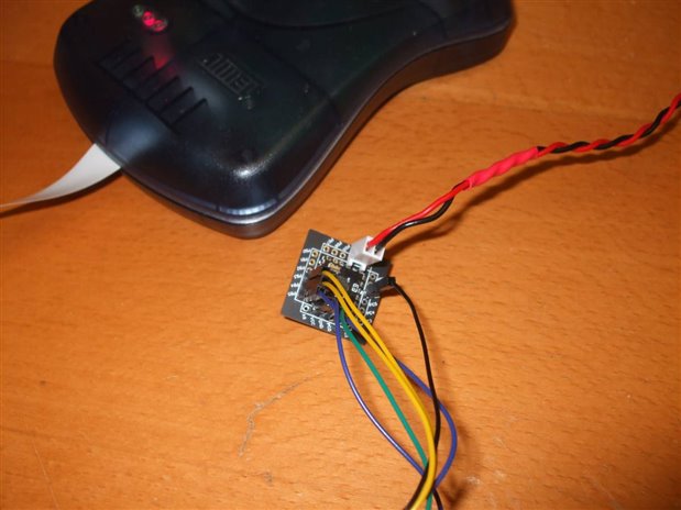
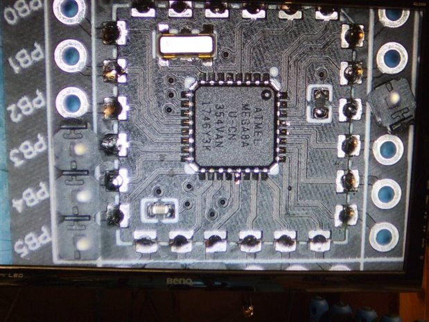
The image on the left is the final thing with it attached and the PCB on the right is what it looks like assembled (i think i have all the components i need on that board for it to be sufficient but again (complete novice at this)


If anyone would be able to help, i can happily supply the Gerber/schematic for what i have named (ATMegaX)


Thanks


What the final result would look likeThe chip in question i am trying to make

  • Sign in to reply
  • Cancel

Top Replies

  • michaelkellett
    michaelkellett over 5 years ago in reply to alexbee13 +9
    How many of these do you need to solder ? You will get the best results if you use leaded solder paste, a stencil to apply it and reflow the boards in a decent oven. If you don't have all these things…
  • shabaz
    shabaz over 5 years ago +5
    Hi, I cannot volunteer to do this, but I can suggest an alternative; if you don't have the tools or experience for this, you're better off ditching the castellated board which makes no sense if it is carrying…
  • fmilburn
    fmilburn over 5 years ago in reply to michaelkellett +4
    Thanks for the tip of using a large hole under the center pad Michael. I hadn’t tried that and getting too much paste without a stencil is easy to do. Also agree that hot air rework is difficult with these…
Parents
  • shabaz
    shabaz over 5 years ago

    Hi,


    I cannot volunteer to do this, but I can suggest an alternative; if you don't have the tools or experience for this, you're better off ditching the castellated board which makes no sense if it is carrying just the microcontroller, crystal and a couple of passive components, and just redesigning the board on the left to carry the TQFP version of the chip, which has fairly large 0.8mm pin spacing, and is hand-solderable with a normal iron, no need for hot air tool skills. The TQFP part will take up less space than the castellated board, so it will fit. It would be a cleaner, lower-profile and more reliable solution.

    Castellated boards kind-of make sense for (say) ESP boards because they contain more circuitry as a module, and also radio circuitry to simplify the end product. Here it's not simplifying, it's making it more complicated.

    Also, the left side board is large, you could also go for a larger crystal and passives, if you feel you have the space for that. I can't tell if you're using 0603 or 0402.. 0402 is more unreliable for manufacture, I don't think it's worth the effort (unless there's a technical reason for using 0402).

    • Cancel
    • Vote Up +5 Vote Down
    • Sign in to reply
    • Cancel
  • alexbee13
    alexbee13 over 5 years ago in reply to shabaz

    Hi, The reason for the Castellated holes version is so that i can use the same module for other projects in the future, Instead of having a full arduino with pin headers taking up valuable room, i could instead go for a module that keeps a low profile while providing everythhing i need, Also i regrettably went with 0402 and it was a terrible mistake, I only have space where it is on the PCB due to how the xbox from panel connects to the front. I guess i could go with the TQFP version as well but preferrably would want to keep with this module idea for future projects.


    Thank you for your feedback though and i guess i could make a prototype using the TQFP version. Also do you suggest any other crystals to use because they are really small and again, hot air rework/soldering those sized modules is really difficult

    • Cancel
    • Vote Up +3 Vote Down
    • Sign in to reply
    • Cancel
  • michaelkellett
    michaelkellett over 5 years ago in reply to alexbee13

    MK Electronics Ltd,

    Unit 4,

    Greenlaw,

    Castle Douglas,

    DG72LH


    I'll look forward to it.


    MK

    • Cancel
    • Vote Up 0 Vote Down
    • Sign in to reply
    • Cancel
  • luislabmo
    luislabmo over 5 years ago in reply to michaelkellett

    I may be the exception to the hot-air rule then because that is all I use without major complications (that includes those tiny QFN chips with thermal pads) image. I think hot-air works well for small PCBs like this one.


    Luis

    • Cancel
    • Vote Up 0 Vote Down
    • Sign in to reply
    • Cancel
  • michaelkellett
    michaelkellett over 5 years ago in reply to alexbee13

    Hello Alex,

    Got the board - post office did their best to wreck it - looks like they used a rolling pin !


    I have pliers - I can fix it !


    image


    MK

    • Cancel
    • Vote Up +1 Vote Down
    • Sign in to reply
    • Cancel
  • alexbee13
    alexbee13 over 5 years ago in reply to michaelkellett

    Oh no!


    Thank you and as you can see in that image, i did not solder the resistor to the pad on the right, the cap is meant to go where it is there but i could not solder 0403 by hand :/


    I provided the resistors and caps as needed and i imagine from that image above you can work out where the resistor and cap goes image


    Thanks

    • Cancel
    • Vote Up 0 Vote Down
    • Sign in to reply
    • Cancel
  • michaelkellett
    michaelkellett over 5 years ago in reply to michaelkellett

    I got it hooked up to an Arduino Uno running the ISP sketch. Downloaded AVRdude, WINAVR, and tried quite hard. I want to like Arduinos but I can't because they never work. Everything is hidden in layer upon layer of mess !

    Any way, AVRdude thought it (Arduino as ISP programmer) was working but reports the ID code for an ATmega328 with anything (or nothing) connected to the ISP pins. (Anything including an ATmega8 on a proto board with no other parts at all).

    I thought that some of the pins on the little target board were possible not well soldered so I re-touched them.

    Left it connected while dealing with a visitor (shooing him out of the works while telling him that the notice on the door about Cronovirus is NOT a joke !)

    Arduino was repeatedly losing USB to the PC and coming back again, the little test board had died image and was drawing lots of current.


    Gave up on Arduino and set ATMEL Studio to install while I soldered a new chip to one of the spare tiny boards and soldered that to the breakout board.

    Connected up using ATMEL-ICE Mk2 from ATMEL Studio. No bother identifying the meg8 on the protp board and no bother with the QFN on the little target board.

    Blew the fuses for 8MHz internal clock operation and put this program in:


    /*
     * GccApplication1.c
     *
     * Created: 20/03/2020 15:09:02
     * Author : Michael Kellett
     */ 
    
    #include <avr/io.h>
    
    
    void delay_ms(int ms)
    {
    volatile int i;
    while(ms-- != 0)
        {
            for(i = 0;i < 200;i++)
            {
                i--;
                i++;
            }
        }
        
    }
    
    
    int main(void)
    {
        /* Replace with your application code */
        DDRC = 0xff;           // Configure PORTC as output
    
        while(1)
        {
            PORTC = 0xff;        // Turn ON all the Leds connected to PORTC
            delay_ms(100);      // Wait for some time
            PORTC = 0x00;        // Turn OFF all the Leds connected to PORTC
            delay_ms(100);      // Wait for some time
        }
    }


    Seems to work OK - get this on port C pin 2:


    image


    Here's a pic of the little board connected to the ATMEL_ICE:

    image


    These are the soldering irons and cheapo Chinese video microscope I used to hand solder the chip on.

    On the left of the microscope base you can see a springy wire held in one of theose Ebay "third hand" things.

    I use that to hold chips down on the board before I solder them - you just poke the chip with tweezers until it's exactly where you want it.

    You can see the iron I used on the left (the ERSA one), and the flux bottle on the right.

    The other thing I do is use really thin leaded solder for hand soldering fine pitch chips (32SWG).

    image


    This is the hand soldered chip on the video microscope screen:


    image


    So my conclusions are:


    Your board is OK and it does work.

    The Arduino Uno as an ISP running under AVRdude is a pile of poo.

    Probably your board wasn't working due to a non soldered joint but because I killed it we'll never be quite sure.

    The chip can be hand soldered OK to your board - if you make more boards you can make the centre pad a bit smaller (so you can't easily short to it.)

    I find green resist boards easier to work with  - it's easier to see things than on black, red or white (might be my eyes !).

    Put things with pins in a box else the postman will tread on them image


    Send me your address and I'll post the goodies back to you (and some fine gauge solder).

    You can get my email from www.mkesc.co.uk


    MK

    • Cancel
    • Vote Up +1 Vote Down
    • Sign in to reply
    • Cancel
  • alexbee13
    alexbee13 over 5 years ago in reply to michaelkellett

    Thank you so much! how many boards did i send to you? and were you able to get the 16MHZ working on them as the Crystal that is external is 16Mhz and would be ideal as i'm going to be using 5V on these boards?


    And I wanted black PCB's because they look cooler (not a good reason i know!)


    And for future reference i will use a box next time to send goods image


    Will email you in a second with my address


    Thanks

    • Cancel
    • Vote Up 0 Vote Down
    • Sign in to reply
    • Cancel
  • alexbee13
    alexbee13 over 5 years ago in reply to michaelkellett

    Also if possible would you be able to not solder the Tiny PCB onto the other test board (unsure if i sent you 2 or not) as that can then go onto the actual PCB i intend to use these on image

    • Cancel
    • Vote Up 0 Vote Down
    • Sign in to reply
    • Cancel
  • michaelkellett
    michaelkellett over 5 years ago in reply to alexbee13

    I've only soldered one tiny pcb  - I've left the other for you to do (but I could do it if you really want.)

    It's a bit hard to test the tiny board on it's own.

    I'll see if the one I've done will work at 16MHz.


    MK

    • Cancel
    • Vote Up 0 Vote Down
    • Sign in to reply
    • Cancel
  • alexbee13
    alexbee13 over 5 years ago in reply to michaelkellett

    Alright and yeah if you don't mind, i would appreciate if you could assemble the other one,


    What microscope do you use btw and that holder thing you mentioned, Now is probably a good time to get one to help with seeing everything properly


    Thanks

    • Cancel
    • Vote Up 0 Vote Down
    • Sign in to reply
    • Cancel
  • michaelkellett
    michaelkellett over 5 years ago in reply to alexbee13

    It does go at 16MHz but only if you solder a decent sized capacitor between the Vcc and Ground pins. I used a 10uF 16V low ERS polymer electrolytic (ceramic would do). With short leads and/or a big cap on the main board it might be OK.


    I'll solder the other board for you.


    My microscope is very like this one:

    https://www.amazon.co.uk/F-JX-Microscope-Industrial-Camera-Repair/dp/B084KMHXQQ/ref=sr_1_14?keywords=hdmi+microscope&qid…

    Best to look around and find one in the UK on decent delivery - check carefully what resolution you are getting from the HDMI and that the stand etc is included.


    MK

    • Cancel
    • Vote Up 0 Vote Down
    • Sign in to reply
    • Cancel
Reply
  • michaelkellett
    michaelkellett over 5 years ago in reply to alexbee13

    It does go at 16MHz but only if you solder a decent sized capacitor between the Vcc and Ground pins. I used a 10uF 16V low ERS polymer electrolytic (ceramic would do). With short leads and/or a big cap on the main board it might be OK.


    I'll solder the other board for you.


    My microscope is very like this one:

    https://www.amazon.co.uk/F-JX-Microscope-Industrial-Camera-Repair/dp/B084KMHXQQ/ref=sr_1_14?keywords=hdmi+microscope&qid…

    Best to look around and find one in the UK on decent delivery - check carefully what resolution you are getting from the HDMI and that the stand etc is included.


    MK

    • Cancel
    • Vote Up 0 Vote Down
    • Sign in to reply
    • Cancel
Children
No Data
element14 Community

element14 is the first online community specifically for engineers. Connect with your peers and get expert answers to your questions.

  • Members
  • Learn
  • Technologies
  • Challenges & Projects
  • Products
  • Store
  • About Us
  • Feedback & Support
  • FAQs
  • Terms of Use
  • Privacy Policy
  • Legal and Copyright Notices
  • Sitemap
  • Cookies

An Avnet Company © 2025 Premier Farnell Limited. All Rights Reserved.

Premier Farnell Ltd, registered in England and Wales (no 00876412), registered office: Farnell House, Forge Lane, Leeds LS12 2NE.

ICP 备案号 10220084.

Follow element14

  • X
  • Facebook
  • linkedin
  • YouTube