element14 Community
element14 Community
    Register Log In
  • Site
  • Search
  • Log In Register
  • About Us
  • Community Hub
    Community Hub
    • What's New on element14
    • Feedback and Support
    • Benefits of Membership
    • Personal Blogs
    • Members Area
    • Achievement Levels
  • Learn
    Learn
    • Ask an Expert
    • eBooks
    • element14 presents
    • Learning Center
    • Tech Spotlight
    • STEM Academy
    • Webinars, Training and Events
    • Learning Groups
  • Technologies
    Technologies
    • 3D Printing
    • FPGA
    • Industrial Automation
    • Internet of Things
    • Power & Energy
    • Sensors
    • Technology Groups
  • Challenges & Projects
    Challenges & Projects
    • Design Challenges
    • element14 presents Projects
    • Project14
    • Arduino Projects
    • Raspberry Pi Projects
    • Project Groups
  • Products
    Products
    • Arduino
    • Avnet Boards Community
    • Dev Tools
    • Manufacturers
    • Multicomp Pro
    • Product Groups
    • Raspberry Pi
    • RoadTests & Reviews
  • Store
    Store
    • Visit Your Store
    • Choose another store...
      • Europe
      •  Austria (German)
      •  Belgium (Dutch, French)
      •  Bulgaria (Bulgarian)
      •  Czech Republic (Czech)
      •  Denmark (Danish)
      •  Estonia (Estonian)
      •  Finland (Finnish)
      •  France (French)
      •  Germany (German)
      •  Hungary (Hungarian)
      •  Ireland
      •  Israel
      •  Italy (Italian)
      •  Latvia (Latvian)
      •  
      •  Lithuania (Lithuanian)
      •  Netherlands (Dutch)
      •  Norway (Norwegian)
      •  Poland (Polish)
      •  Portugal (Portuguese)
      •  Romania (Romanian)
      •  Russia (Russian)
      •  Slovakia (Slovak)
      •  Slovenia (Slovenian)
      •  Spain (Spanish)
      •  Sweden (Swedish)
      •  Switzerland(German, French)
      •  Turkey (Turkish)
      •  United Kingdom
      • Asia Pacific
      •  Australia
      •  China
      •  Hong Kong
      •  India
      •  Korea (Korean)
      •  Malaysia
      •  New Zealand
      •  Philippines
      •  Singapore
      •  Taiwan
      •  Thailand (Thai)
      • Americas
      •  Brazil (Portuguese)
      •  Canada
      •  Mexico (Spanish)
      •  United States
      Can't find the country/region you're looking for? Visit our export site or find a local distributor.
  • Translate
  • Profile
  • Settings
Arduino
  • Products
  • More
Arduino
Arduino Forum Pokémon Tamagotchi using Digispark - Help needed
  • Blog
  • Forum
  • Documents
  • Quiz
  • Events
  • Polls
  • Files
  • Members
  • Mentions
  • Sub-Groups
  • Tags
  • More
  • Cancel
  • New
Join Arduino to participate - click to join for free!
Actions
  • Share
  • More
  • Cancel
Forum Thread Details
  • Replies 9 replies
  • Subscribers 393 subscribers
  • Views 1942 views
  • Users 0 members are here
  • pokemon
  • help
  • diy
  • gameboy
  • digispark
  • arduino
Related

Pokémon Tamagotchi using Digispark - Help needed

herrlichakafool
herrlichakafool over 11 years ago

Hello element14 community,


i found an old Gameboy Color in my basement with Pokémon Red in it, and since i am looking for a project for quite a while now,

i am willing to sacrifice it for the sake of modding.


Since my knowledge of electronics is basic, i hoped that some of you could help me out.

But first let explain my idea:


There used to be an interactive stream on twitch.com which allowed all viewers to play Pokémon at the same time.

People where able to enter one of 7 commands in the chat (Up, Down, Left, Right, Start, A, B),

which where then interpreted as commands for an emulator running Pokémon.


Example:

TwitchPlaysPokemon - Twitch Plays Pokemon (Red) 12d20h37m ~ 14d14h50m - Twitch


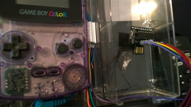
These semi-random inputs led to hillarious moments, which i want to recreate (sort of) by using an old Gameboy Color and a Digispark.


The idea is that the Digispark (which is a tiny Arduino-like microcontroller) enters random key inputs into the Gameboy, so it plays the game for itself.

When i started this project, i soon ran into some problems that i can't solve myself:
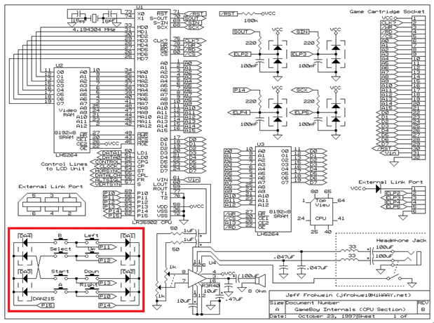
 

1. The schematics:


I generally know how to do it, but when it comes to really doing it, i fail. My Digispark can deliver 5V on each pin, when i measured the voltage on each button

i got about 3.4V. The output of the Digispark can be regulated, but i am sure that i need some resistors in my project. Any ideas?


2. Not enough pins


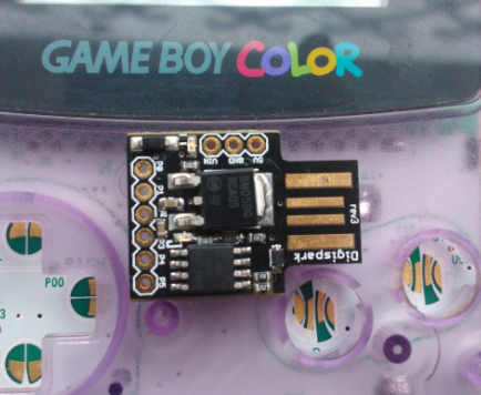
Here is a 3D render of a Digispark.

digispark-mini-arduino-newdesign.jpeg

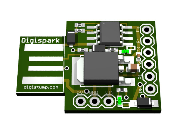
As you can see, it has 6 pins. But the project requires 7 output sources. This could probably be done by creating a matrix, but again my knowledge is not advanced enough. Can someone give me a hint?


I would be really thankful for any kind of response. I don't want to accidentally trash my Gameboy, that's why i created this post.

  • Sign in to reply
  • Cancel

Top Replies

  • Former Member
    Former Member over 11 years ago in reply to herrlichakafool +1
    I'm the creator of the Digispark - to clear up a few things: The Digispark is an ATTINY development board it uses the Attiny85 microcontroller and allows it to be programmed over USB with the Arduino IDE…
  • nschreiber0813
    nschreiber0813 over 11 years ago

    Dear: Theo

    I see what your problem is. Would it hurt to just use a different microcontroller or am I missing something. Microcontroller ATTINY would work fairly good for this.

    From: Noah

    Adafruit Trinket - Mini Microcontroller - 5V Logic

    • Cancel
    • Vote Up 0 Vote Down
    • Sign in to reply
    • Cancel
  • herrlichakafool
    herrlichakafool over 11 years ago in reply to nschreiber0813

    Hey,

    thanks for the reply. What advantages would an ATTINY have? In general it would be great if the microcontroller would fit somewhere inside the housing of the Gameboy.

    • Cancel
    • Vote Up 0 Vote Down
    • Sign in to reply
    • Cancel
  • nschreiber0813
    nschreiber0813 over 11 years ago in reply to herrlichakafool

    Dear: Theo

    There are many advantages towards using atmega Atiny. First of all attiny is small and can probably fit in your gameboy. Second of all it has more pins so it will solve your problem. Third reason is that it can preform well enough to fill your needs. The only problem with it is that you are going to need to design a PCB to fit your needs but you already were going to do that since you choose the project you choose.

    From: Noah

    • Cancel
    • Vote Up 0 Vote Down
    • Sign in to reply
    • Cancel
  • herrlichakafool
    herrlichakafool over 11 years ago in reply to nschreiber0813

    Does an Atiny really have more pins?

    And a Digispark does fit just beautifully inside the Gameboy housing.

    I have several of these laying around in my home, so i thought it would be reasonable to use them.


    Besides, do i really need to order a custom PCB? There would not be much circuitry added exept

    some resistors, at least that's what i think.

    20871c5ee39c5db6c6878b4ef3329e82.png

    331bf6d637315e130256e3f072c60695.png

    • Cancel
    • Vote Up 0 Vote Down
    • Sign in to reply
    • Cancel
  • Former Member
    Former Member over 11 years ago in reply to herrlichakafool

    I'm the creator of the Digispark - to clear up a few things:


    The Digispark is an ATTINY development board it uses the Attiny85 microcontroller and allows it to be programmed over USB with the Arduino IDE


    The Trinket made by Adafruit - which is what Noah posted a photo of - is exactly the same hardware - Adafruit released this version after the Digispark's success. The Digispark has a much bigger user community behind it at digistump.com/board


    The Digispark you have pictured is a counterfiet clone - you can tell because it does not have our web address "digistump.com" on the back. Most of these don't work or fail quickly due to improper parts (mostly the zener diodes and protection diode). If you'd like to get the real thing go to digistump.com - we also support all users of real digisparks through our wiki at digistump.com/wiki and our forums at digistump.com/board


    You may be able to do something like this to get two outputs from one pin: Batsocks - Controlling Two LEDs per uC pin


    We also sell a expander kit that adds 8 more outputs to the Digispark


    To get your 5v outputs to 3.5v you could use a resistor divider (voltage divider), you could put a 3.5v zener diode from that pin to ground, or you could use a level shifter chip.


    Hope that helps direct you down the right path.

    • Cancel
    • Vote Up +1 Vote Down
    • Sign in to reply
    • Cancel
  • herrlichakafool
    herrlichakafool over 11 years ago in reply to Former Member

    Thank you for your reply Erik!

    When i purchased my Digispark i did not know that it was a fake, sorry about that. Just got one from ebay since it was the easiest way do purchase one.

    Also thanks for your hint about using a resistor divider, i will read into it.


    It seems that the expander kit is the most straight foward  way of doing it, that's why i ordered an original Digispark + I/O expansion.

    Some workaround has to be made since the depth of the expansion ontop of the Digispark probably makes it too bulky to fit at the spot i intended it to be.

    • Cancel
    • Vote Up 0 Vote Down
    • Sign in to reply
    • Cancel
  • Former Member
    Former Member over 11 years ago in reply to herrlichakafool

    Theo -


    Thanks for your support!


    You can wire the expander shield with wire so that you can place it anywhere - just connect Digispark -> Expander as follows:

    GND->GND

    5V->5V

    P0->P0

    P2->P2


    Those are all the connections needed for the expander.


    Thanks,

    Erik

    • Cancel
    • Vote Up 0 Vote Down
    • Sign in to reply
    • Cancel
  • herrlichakafool
    herrlichakafool over 10 years ago

    Hey,


    it took some time for me to update my project, but here we go:


    I soldered really thin wire to some testing points on the board of the gameboy for following pins, with their randromized chance to be pressed in brackets:


    1. Ground image

    2. Up (25/200)

    3. Down (25/200)

    4. Left (25/200)

    5. Right (25/200)

    6. A (50/200)

    7. B (40/200

    8. Start (10/200)

    image

    image


    He runs like a charm, with the Digispark hanging on an USB source and the Gameboy on a 3V 200mA power brick.

    Now again, any tips how to run both on one source? I have plenty of spare power bricks with differentvoltages, so any tip would help.


    Besides, i want to add some type of lightsource, maybe a LED strip. Also if you want to know, he is still at the first town and can't make it to the second town and he has a level 43 Bulbasaur,so he didn't evolve image

    In addition, i want to add some sort if input to control the chances of a button to be pressed, maybe some Potentiometers? I imagine them to be placed in between Gameboy and micro controller, so it can read the resistance.

    Are the pins capable to pull this off?


    Would like to get some feedback from you, i'll keep you up to date.


    Best Regards,

    Theo

    • Cancel
    • Vote Up 0 Vote Down
    • Sign in to reply
    • Cancel
  • herrlichakafool
    herrlichakafool over 10 years ago

    Hey,


    after some time i started to get back to my old project, but this time using a Gameboy Classic, since it would fit perfectly into the box i posted above.

    But quickly after starting i ran into a problem.

    It seems like the old Gameboy Classic uses a more complex circuit when it comes to button inputs, as you can see here:

    image

    In my first attempt i just connected both grounds of the Digispark and the Gameboy Color, and i wired each button i needed to a digital pin.

    Unfortunately this does not work on the classical Gameboy.


    I still have problems with the power management, but since the Gameboy Classic uses 4 AA batteries, it would come closer to the 5V needed for the Digispark.

    Luckily i found a spot where an Arduino Micro would fit inside, so it can be one unit insdead of the ugly workaround i used on my first attempt.


    image

    image

    So, if anyone could help me on this project i would be very thankful.


    Best regards,

    Theo

    • Cancel
    • Vote Up 0 Vote Down
    • Sign in to reply
    • Cancel
element14 Community

element14 is the first online community specifically for engineers. Connect with your peers and get expert answers to your questions.

  • Members
  • Learn
  • Technologies
  • Challenges & Projects
  • Products
  • Store
  • About Us
  • Feedback & Support
  • FAQs
  • Terms of Use
  • Privacy Policy
  • Legal and Copyright Notices
  • Sitemap
  • Cookies

An Avnet Company © 2025 Premier Farnell Limited. All Rights Reserved.

Premier Farnell Ltd, registered in England and Wales (no 00876412), registered office: Farnell House, Forge Lane, Leeds LS12 2NE.

ICP 备案号 10220084.

Follow element14

  • X
  • Facebook
  • linkedin
  • YouTube