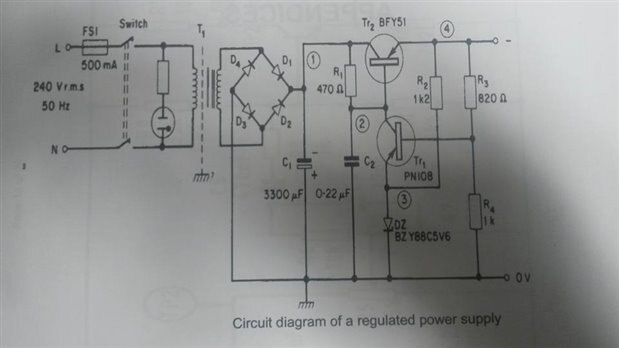
Cant seem to find a problem here or improvements but i know there should be one! could you please help me
Your schematic shows you're using a PNP for TR1 and TR2 and it should be a NPN., the part numbers are NPN so are these the parts your using.
A PNP transistor will flow current from emitter to collector, An NPN is Collector to Emitter (I know,..... i'm using practical Electronics, not Real electron flow)
So you need to change it to an NPN. This is assuming the schematic is correct real components are not. And not just a drawing error with the diagram
Secondly the PN108 is a photo transistor from all the data sheets I have found and as such will be very susceptible to light turning it on and off you should not be using this device for this circuit use a BC108 or 2N22222N2222 or any other general purpose NPN transistor just not a photo transistor It probably looks like it has a glass top or plastic semi transparent top on it
You did not say what was the behaviour of you circuit and why you thought it was not working
Hope this will help, the rest on first scan looks correct.
Im betting you got these transistors from re-cycled boards or obsolete parts ??
this diagram is for a proposed new d.c regulated power supply. it is required to produce a negative voltage of -14V with respect to ground. Thanks by the way for you help! can you spot anything else or is that all?
this diagram is for a proposed new d.c regulated power supply
Sorry but I'm still sceptical about this.
Who is supplying this new power supply, and why are we doing the checking for you.??