element14 Community
element14 Community
    Register Log In
  • Site
  • Search
  • Log In Register
  • About Us
  • Community Hub
    Community Hub
    • What's New on element14
    • Feedback and Support
    • Benefits of Membership
    • Personal Blogs
    • Members Area
    • Achievement Levels
  • Learn
    Learn
    • Ask an Expert
    • eBooks
    • element14 presents
    • Learning Center
    • Tech Spotlight
    • STEM Academy
    • Webinars, Training and Events
    • Learning Groups
  • Technologies
    Technologies
    • 3D Printing
    • FPGA
    • Industrial Automation
    • Internet of Things
    • Power & Energy
    • Sensors
    • Technology Groups
  • Challenges & Projects
    Challenges & Projects
    • Design Challenges
    • element14 presents Projects
    • Project14
    • Arduino Projects
    • Raspberry Pi Projects
    • Project Groups
  • Products
    Products
    • Arduino
    • Avnet Boards Community
    • Dev Tools
    • Manufacturers
    • Multicomp Pro
    • Product Groups
    • Raspberry Pi
    • RoadTests & Reviews
  • Store
    Store
    • Visit Your Store
    • Choose another store...
      • Europe
      •  Austria (German)
      •  Belgium (Dutch, French)
      •  Bulgaria (Bulgarian)
      •  Czech Republic (Czech)
      •  Denmark (Danish)
      •  Estonia (Estonian)
      •  Finland (Finnish)
      •  France (French)
      •  Germany (German)
      •  Hungary (Hungarian)
      •  Ireland
      •  Israel
      •  Italy (Italian)
      •  Latvia (Latvian)
      •  
      •  Lithuania (Lithuanian)
      •  Netherlands (Dutch)
      •  Norway (Norwegian)
      •  Poland (Polish)
      •  Portugal (Portuguese)
      •  Romania (Romanian)
      •  Russia (Russian)
      •  Slovakia (Slovak)
      •  Slovenia (Slovenian)
      •  Spain (Spanish)
      •  Sweden (Swedish)
      •  Switzerland(German, French)
      •  Turkey (Turkish)
      •  United Kingdom
      • Asia Pacific
      •  Australia
      •  China
      •  Hong Kong
      •  India
      •  Korea (Korean)
      •  Malaysia
      •  New Zealand
      •  Philippines
      •  Singapore
      •  Taiwan
      •  Thailand (Thai)
      • Americas
      •  Brazil (Portuguese)
      •  Canada
      •  Mexico (Spanish)
      •  United States
      Can't find the country/region you're looking for? Visit our export site or find a local distributor.
  • Translate
  • Profile
  • Settings
Arduino
  • Products
  • More
Arduino
Arduino Forum Replacing a device's button with an Arduino
  • Blog
  • Forum
  • Documents
  • Quiz
  • Events
  • Polls
  • Files
  • Members
  • Mentions
  • Sub-Groups
  • Tags
  • More
  • Cancel
  • New
Join Arduino to participate - click to join for free!
Actions
  • Share
  • More
  • Cancel
Forum Thread Details
  • State Verified Answer
  • Replies 30 replies
  • Answers 11 answers
  • Subscribers 393 subscribers
  • Views 4993 views
  • Users 0 members are here
  • arduino uno
  • arduino_tutorials
  • advice
  • costume
Related

Replacing a device's button with an Arduino

talongrayson
talongrayson over 8 years ago

Hi,


Let me start by saying that I'm fairly new to electronics, and I may get some terminology wrong in this post. I'll do my best to ensure it makes sense, though, and please feel free to correct me where necessary as I am very keen to learn.


As the title (vaguely) suggests, I am working on a project in which I need to - for want of a better description - replace a device's 'push to make' switch with an Arduino Uno.


The project is actually the glove of a costume I am building. It is going to release 'smoke' when the wearer's hand is in specified positions. The setup isn't hugely complicated, and I believe I have everything straight in my head except for one thing. I'll start by explaining the setup...


In the glove I have an accelerometer, and with my Arduino sketch I can define gestures and recognise those gestures.


I've built a basic shield for the Arduino with a transistor so that I can control a blower fan. The Arduino and fan are powered by a 9v battery which connects to this shield. I've essentially enclosed the blower fan so that its inlet is connected to a 'vape' (you know, one of those e-cigarette type things).


So far I have got everything working, but the vape is not connected to the Arduino in any way. In fact, it hasn't even arrived yet, so while awaiting its delivery I've been considering how I might connect it all up.

The intention is to have the fan and some LEDs turn on and the vape button pressed when a specific gesture is made. The vape will heat up, the fan will suck vapor through the tubes, and the vapor will emerge from the glove. When the gesture is no longer being made, the fan turns off and the vape button is released.


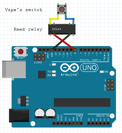
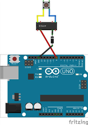
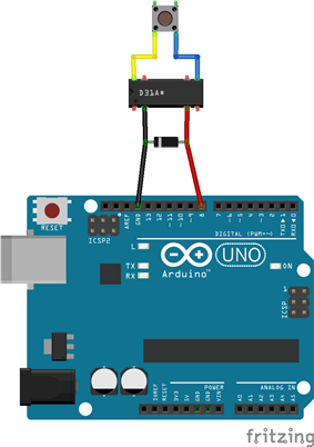
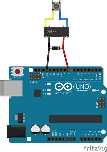
I've gone through a couple of options in my head, including things like having the Arduino control a servo which mechanically presses the button on the vape, but what I'd really like is it pretty much desolder the vape's switch, remove it from the vape, and solder wire at its connections which then connect to the Arduino... or thereabouts, if you see what I mean.


So I'm here to get some advice on what would be the best way to approach this. Is it possible? Trivial? Will I need to use a transistor, a DAC, a relay, or some other method?


Any help would be greatly appreciated and I am more than happy to elaborate further if needs be.

  • Sign in to reply
  • Cancel

Top Replies

  • talongrayson
    talongrayson over 8 years ago +3
    The reed relay arrived today. To cut a long story short, it works like a charm. Next step is to migrate that part of the circuit to the shield. In due course I will upload photos/video to show it in action;…
  • jlangbridge
    jlangbridge over 8 years ago in reply to talongrayson +2 verified
    Aha... So there is a bit of logic there, this isn't a simple on/off switch (I'm not a vaper either, so I had no idea). Well, maybe the "easiest" solution would be to use a relay. There are several types…
  • jlangbridge
    jlangbridge over 8 years ago in reply to talongrayson +2
    Possibly, but I still need a bit of information first; the amount of power required to activate the switch. The relay itself is powered by a coil, and that coil requires power, but a lot of relays require…
Parents
  • talongrayson
    0 talongrayson over 8 years ago

    Progress so far:
    I have soldered wires to 2 pins of the vape device (essentially the blue and yellow wires in the below diagram). I have run those wires to a breadboard with a switch, and that switch can now act as the FIRE switch on the device itself.


    I have ordered a reed relay and intend to wire it as below. I will probably stick a 2-pin JST between the relay and the vape for convenience.

    image


    If this goes to plan, all that remains is the actual costume itself. And of course, if it works, jlangbridge answer will be marked as correct.

    • Cancel
    • Vote Up 0 Vote Down
    • Sign in to reply
    • Verify Answer
    • Reject Answer
    • Cancel
  • jlangbridge
    0 jlangbridge over 8 years ago in reply to talongrayson

    Hi there! Sorry, the weekend was a little more hectic than expected. Looks good, but I am a little worried about one thing. I'm not too sure the Arduino can supply enough current to be able to activate the reed switch. I don't have any, so I can't check. If it doesn't work, there is something else you can try; instead of connecting one of the pins to GND, connect it to the 5V supply. You will need to change the code slightly; if the "output" is high, then no current will flow. If the "output" is low, then current will flow from the 5V rail to the pin (this is known as active low). The problem will all of this is that the MCU can only provide (and sink) a certain amount of current before damage can occur. Another thing to take into account is the use of a snubber diode; when electromagnetic fields collapse, they can sometimes generate a spike of current. Some reed relays actually have one built in.


    That being said, everything looks good! You have effectively put a switch in parallel, so you should be good to go as soon as you confirm the timing is good, but that is only a software tweak.

    • Cancel
    • Vote Up 0 Vote Down
    • Sign in to reply
    • Verify Answer
    • Reject Answer
    • Cancel
Reply
  • jlangbridge
    0 jlangbridge over 8 years ago in reply to talongrayson

    Hi there! Sorry, the weekend was a little more hectic than expected. Looks good, but I am a little worried about one thing. I'm not too sure the Arduino can supply enough current to be able to activate the reed switch. I don't have any, so I can't check. If it doesn't work, there is something else you can try; instead of connecting one of the pins to GND, connect it to the 5V supply. You will need to change the code slightly; if the "output" is high, then no current will flow. If the "output" is low, then current will flow from the 5V rail to the pin (this is known as active low). The problem will all of this is that the MCU can only provide (and sink) a certain amount of current before damage can occur. Another thing to take into account is the use of a snubber diode; when electromagnetic fields collapse, they can sometimes generate a spike of current. Some reed relays actually have one built in.


    That being said, everything looks good! You have effectively put a switch in parallel, so you should be good to go as soon as you confirm the timing is good, but that is only a software tweak.

    • Cancel
    • Vote Up 0 Vote Down
    • Sign in to reply
    • Verify Answer
    • Reject Answer
    • Cancel
Children
  • talongrayson
    0 talongrayson over 8 years ago in reply to jlangbridge

    No problem at all about the delay - I've enjoyed looking into this stuff!
    Thanks for the active low tip. I'll bear that in mind if things don't work properly. And as for a snubber, I have some 1N4004 rectifier diodes here which I can use.  If I've learned well enough, the below diagram should be correct.


    Just gotta wait for the relay to arrive and I can see if it works! image


    image

    • Cancel
    • Vote Up 0 Vote Down
    • Sign in to reply
    • Verify Answer
    • Cancel
  • jlangbridge
    0 jlangbridge over 8 years ago in reply to talongrayson

    Not quite! The diode will be between the relay's coil pins. Have a look at the Wikipedia page, the first schematic.

    https://en.wikipedia.org/wiki/Flyback_diode

    When the coil is powered, the diode is useless, but when the coil is powered down, any inverse energy caused by the magnetic field breakdown gets shorted out.

    • Cancel
    • Vote Up +1 Vote Down
    • Sign in to reply
    • Verify Answer
    • Reject Answer
    • Cancel
  • talongrayson
    0 talongrayson over 8 years ago in reply to jlangbridge

    I think I'm confused... like this?

    image

    • Cancel
    • Vote Up 0 Vote Down
    • Sign in to reply
    • Verify Answer
    • Cancel
  • jlangbridge
    0 jlangbridge over 8 years ago in reply to talongrayson

    The other way around, the "illogical" way. The way you put it, if you power up pin 8, it will go through the diode, and to ground. If you put the diode the other way around, then the diode will block the flow, and basically do nothing. The problem happens when you shut down the electromagnetic field. EM fields don't like change, and will fight to keep things the way they are. If you power down the relay coil, it sometimes creates an inverse, essentially putting a + on the ground pin, and a - on pin 8, where there used to be a +. As you can imagine, even if it is extremely brief, it can cause damage to the board. To counter this, we use a diode. If the current is in the "normal" position, ie you are powering the coil, then it doesn't do anything. If you shut down the coil and the coil fights back, then it will short out the difference, protecting your Arduino. I'd add a few sketches, but I can't where I am right now...

    • Cancel
    • Vote Up 0 Vote Down
    • Sign in to reply
    • Verify Answer
    • Reject Answer
    • Cancel
  • talongrayson
    0 talongrayson over 8 years ago in reply to jlangbridge

    Yep, that's "illogical". The thing is, I had it the other way around in the first place, thinking that's what you meant. Then the more I analysed the circuit and tried to understand it, the more it seemed like it should be the other way around. Not sure whether that was just newbie confusion or what, but hey, if it's correct then who am I to argue? image


    For completeness I've added the latest version of the diagram. Thank you once again for all your help. I'll let you know the results as soon as I have something to share.


    image

    • Cancel
    • Vote Up +1 Vote Down
    • Sign in to reply
    • Verify Answer
    • Cancel
  • jc2048
    0 jc2048 over 8 years ago in reply to jlangbridge

    "When the coil is powered, the diode is useless, but when the coil is powered down, any inverse energy caused by the magnetic field breakdown gets shorted out."


    I suspect that you'll find, in this case, the diode is always useless. The internal anti-static protection diode for the IO pin (it's in parallel with your external one) will have a lower Vf and will dissipate the coil's energy.

    • Cancel
    • Vote Up 0 Vote Down
    • Sign in to reply
    • Verify Answer
    • Reject Answer
    • Cancel
  • jlangbridge
    0 jlangbridge over 8 years ago in reply to jc2048

    So you can confirm that he doesn't actually need a snubber diode here?

    • Cancel
    • Vote Up 0 Vote Down
    • Sign in to reply
    • Verify Answer
    • Cancel
  • jc2048
    0 jc2048 over 8 years ago in reply to jlangbridge

    No. I said I suspect. I can't know for sure how Atmel have implemented the anti-static protection, but the most common way is to utilise metal-barrier diodes that arise naturally as part of the process and don't cost the manufacturer anything (they're Schottky diodes and the forward voltage would be something like 0.2V or 0.3V at the relay current).


    It's not good design practice to use the internal diodes like this, which I think is why the manufacturers are a bit coy about giving specs on them.


    In practice, for a personal project, the microcontroller would manage. With a 500ohm coil, the max current is only 10mA and with such a low repetition rate the dissipation is next to nothing.


    The biggest disadvantage is a side effect: the slow release of the relay. The 0.3V means that the initial dissipation is low (10mA x 0.3 = 3mW) and the current through the coil will fall slowly. So the release of the contact, when it comes, will be slow and if it's switching a high current there may be problems with the contacts after you've done it a few times.

    • Cancel
    • Vote Up 0 Vote Down
    • Sign in to reply
    • Verify Answer
    • Reject Answer
    • Cancel
  • jc2048
    0 jc2048 over 8 years ago in reply to jlangbridge

    I've just looked at the protection on an Arduino pin and it turns out I am wrong.


    Here's pin '8' set to be an input and driven with a sine wave that goes outside the supply range (with a series resistor to limit the current). Ground is where the '2' marker is, so we are looking at negative voltages. The yellow trace is the sine wave, the blue trace is the voltage that the protection network in the chip is clamping it to. It's a much larger voltage than I would have thought (about -780mV at the centre, at a current of around 8.5mA), so I'm quite wrong about how they are doing it.


    image


    Here it is with an external 1N4004 added, and the external diode is having an effect - its forward voltage is coming in at less than the protection network.


    image


    Ok, that's for an input. But what if you don't turn it back to an input when you don't want the coil to be powered but just set the output to be low? In that case we get this


    image


    because the MOSFET channel is bidirectional and will clamp the input to ground even when it goes negative. I've now raised the current at the centre to about 10mA and you can see that the voltage is now about -180mV. That gives a dynamic resistance for the MOSFET of about 18 ohms, which is about right for a processor IO pin.

    • Cancel
    • Vote Up +1 Vote Down
    • Sign in to reply
    • Verify Answer
    • Reject Answer
    • Cancel
  • talongrayson
    0 talongrayson over 8 years ago in reply to jc2048

    Not going to lie, I mostly don't understand your post, though I do find it intriguing and would like to understand it. But for now, is the outcome that I need the diode there and my current setup is all good?


    As discussed before, I am using pin 8 as an output and using digitalWrite(8, LOW) when I don't want the coil to be powered.

    • Cancel
    • Vote Up +2 Vote Down
    • Sign in to reply
    • Verify Answer
    • Cancel
element14 Community

element14 is the first online community specifically for engineers. Connect with your peers and get expert answers to your questions.

  • Members
  • Learn
  • Technologies
  • Challenges & Projects
  • Products
  • Store
  • About Us
  • Feedback & Support
  • FAQs
  • Terms of Use
  • Privacy Policy
  • Legal and Copyright Notices
  • Sitemap
  • Cookies

An Avnet Company © 2025 Premier Farnell Limited. All Rights Reserved.

Premier Farnell Ltd, registered in England and Wales (no 00876412), registered office: Farnell House, Forge Lane, Leeds LS12 2NE.

ICP 备案号 10220084.

Follow element14

  • X
  • Facebook
  • linkedin
  • YouTube