element14 Community
element14 Community
    Register Log In
  • Site
  • Search
  • Log In Register
  • About Us
  • Community Hub
    Community Hub
    • What's New on element14
    • Feedback and Support
    • Benefits of Membership
    • Personal Blogs
    • Members Area
    • Achievement Levels
  • Learn
    Learn
    • Ask an Expert
    • eBooks
    • element14 presents
    • Learning Center
    • Tech Spotlight
    • STEM Academy
    • Webinars, Training and Events
    • Learning Groups
  • Technologies
    Technologies
    • 3D Printing
    • FPGA
    • Industrial Automation
    • Internet of Things
    • Power & Energy
    • Sensors
    • Technology Groups
  • Challenges & Projects
    Challenges & Projects
    • Design Challenges
    • element14 presents Projects
    • Project14
    • Arduino Projects
    • Raspberry Pi Projects
    • Project Groups
  • Products
    Products
    • Arduino
    • Avnet Boards Community
    • Dev Tools
    • Manufacturers
    • Multicomp Pro
    • Product Groups
    • Raspberry Pi
    • RoadTests & Reviews
  • Store
    Store
    • Visit Your Store
    • Choose another store...
      • Europe
      •  Austria (German)
      •  Belgium (Dutch, French)
      •  Bulgaria (Bulgarian)
      •  Czech Republic (Czech)
      •  Denmark (Danish)
      •  Estonia (Estonian)
      •  Finland (Finnish)
      •  France (French)
      •  Germany (German)
      •  Hungary (Hungarian)
      •  Ireland
      •  Israel
      •  Italy (Italian)
      •  Latvia (Latvian)
      •  
      •  Lithuania (Lithuanian)
      •  Netherlands (Dutch)
      •  Norway (Norwegian)
      •  Poland (Polish)
      •  Portugal (Portuguese)
      •  Romania (Romanian)
      •  Russia (Russian)
      •  Slovakia (Slovak)
      •  Slovenia (Slovenian)
      •  Spain (Spanish)
      •  Sweden (Swedish)
      •  Switzerland(German, French)
      •  Turkey (Turkish)
      •  United Kingdom
      • Asia Pacific
      •  Australia
      •  China
      •  Hong Kong
      •  India
      •  Korea (Korean)
      •  Malaysia
      •  New Zealand
      •  Philippines
      •  Singapore
      •  Taiwan
      •  Thailand (Thai)
      • Americas
      •  Brazil (Portuguese)
      •  Canada
      •  Mexico (Spanish)
      •  United States
      Can't find the country/region you're looking for? Visit our export site or find a local distributor.
  • Translate
  • Profile
  • Settings
Arduino
  • Products
  • More
Arduino
Arduino Forum Read data input from shift register
  • Blog
  • Forum
  • Documents
  • Quiz
  • Events
  • Polls
  • Files
  • Members
  • Mentions
  • Sub-Groups
  • Tags
  • More
  • Cancel
  • New
Join Arduino to participate - click to join for free!
Actions
  • Share
  • More
  • Cancel
Forum Thread Details
  • State Suggested Answer
  • Replies 19 replies
  • Answers 3 answers
  • Subscribers 393 subscribers
  • Views 2300 views
  • Users 0 members are here
  • shift register
  • multiplexing
  • frontpage
Related

Read data input from shift register

tim687
tim687 over 8 years ago

I am having some troubles getting the readouts from the shift register.

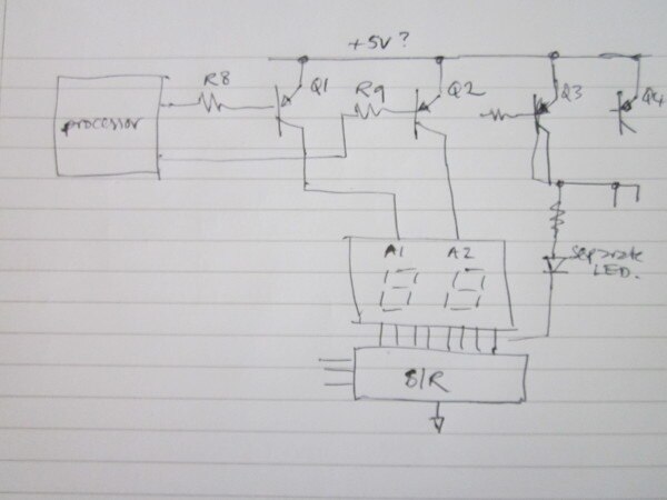
The 74HC_HCT164 controls a EADCD040YA2 (or alike) two digit 7 segment display.

Is there any way that I could reliably read the Serial input data from the shift register.


I have got a pin-out of the shift register to the display, so that shouldn't be any problem.


What might be useful to know, is that the shift register circuit is not only used for the display, but also for some of the LED's.

The data is shifted into the shift register, then the first common anode is turned on by the microprocessor, then the shiftregister latches, shift register clears, second diigit data get's shifted in, second common anode is turned on, shift register latches and shift register clears.


I don't know if there is happening anything between the two digit 'shift's' and what's the clock cycle of the whole circuit. I don't have access to an ocsilloscope, well, I do if you call my Arduino one.


I am using an Arduino to read out the code (using the following sketch: https://pastebin.com/8fWA6qUP)


I would appriciate it very much if anyone could help me out with this problem!


So to be clear: this is NOT about using a shift register the normal way, but to basically hack shift register and read what's being send to it!


Tim

  • Sign in to reply
  • Cancel

Top Replies

  • mcb1
    mcb1 over 8 years ago +1 suggested
    tim687 The 74HCT164 is a serial to parallel converter. Basically you set the state you want on that particular output using the two inputs and then raise the clock. You need to do this 8 times to replace…
  • mcb1
    mcb1 over 8 years ago in reply to tim687 +1 suggested
    Is this related to this. Detect whether a pin is connected to GND I posted a link where a local person has been able to detect the serial output from an Aircon unit. https://nicegear.co.nz/blog/hacking…
  • mcb1
    0 mcb1 over 8 years ago in reply to tim687

    Besided checking both inputs, any other options

    Not really.

    If this is the same circuit as you gave in the other link, then there is a single Input data line, and a clock.

    There must be a second select line for the digits.


    A Parallel to Serial will simply give you back the input data, and you still need to read it.

    Googling Binary to BCD gives lots of hits but nothing really sticks out.


    Mark

    • Cancel
    • Vote Up 0 Vote Down
    • Sign in to reply
    • Verify Answer
    • Cancel
  • tim687
    0 tim687 over 8 years ago in reply to mcb1

    The schematic isn't fully complete, but for a parallel to serial chip, how do I deal with the two digits being send? Do I need to connect the clock signals from the original register to the parallel to serial one?

    • Cancel
    • Vote Up 0 Vote Down
    • Sign in to reply
    • Verify Answer
    • Cancel
  • mcb1
    0 mcb1 over 8 years ago in reply to tim687

    Do I need to connect the clock signals from the original register to the parallel to serial one

    Yes and there is the issue.

    You actually don't really save anything in terms of pin numbers.

    • Cancel
    • Vote Up 0 Vote Down
    • Sign in to reply
    • Verify Answer
    • Cancel
  • tim687
    0 tim687 over 8 years ago in reply to mcb1


    I do if I use the inverse of a shiftregister (shift in register), right?

    • Cancel
    • Vote Up 0 Vote Down
    • Sign in to reply
    • Verify Answer
    • Cancel
  • michaelkellett
    0 michaelkellett over 8 years ago in reply to tim687

    I don't think you'll ever pull this off without a scope or  a logic analyzer.


    A scope may well be outside your budget but you may be able to afford a cheap logic analyzer.


    hobby components usb 8ch 24mhz 8 channel logic analyser. compatible with saleae software.


    This one is typical of the cheapest - it's limited to 24MHz which might be a problem (the clock to the shift register might be faster than this). I haven't used it so it may be rubbish - look for reviews.


    To sort out how the display drive is working you need  to monitor the clock, data and anode signals - so you need at least 4 channels - once you know the protocol you may be able to decode what is sent with less.


    MK

    • Cancel
    • Vote Up 0 Vote Down
    • Sign in to reply
    • Verify Answer
    • Reject Answer
    • Cancel
  • mcb1
    0 mcb1 over 8 years ago in reply to michaelkellett

    you need  to monitor the clock, data and anode signals - so you need at least 4 channels

    If the circuit is the same as the link the two data inputs are paralleled, so 3 channels, but yes otherwise I agree a logic probe or scope is required.


    Mark

    • Cancel
    • Vote Up 0 Vote Down
    • Sign in to reply
    • Verify Answer
    • Cancel
  • jc2048
    0 jc2048 over 8 years ago in reply to tim687

    Tim Koers wrote:


    I've created a little schematic, the output pins of the shiftregister Q0-Q7 (in order) corresponds to the pins A-G and DP.

    I've also figured out which pin controls which segment, but the strange thing is that there is no correlation between the serial input and the expected serial input according to my pin to segment research.


    I got it working at some point, but only for a few numbers. (17, 21, 23, 25, 26, 27)


    Is there something I might be missing?

    Can you have a look and see what the part number of Q1 and Q2 is?


    Most likely the circuit is something like this, with Q1 and Q2 being PNP transistors:


    image


    The 7-seg display is in two halves. The display of one digit is done first, then the other. The transistors enable whichever display is the right one for the data that has just been loaded into the shift register. If I'm right with the circuit, the processor will normally hold all the base drives high and take just one of them low to enable.


    The circuit is actually even more complicated, because the separate LEDs are driven the same way as the 7-segment LEDs and will have their turn too, probably enabled with Q3 or Q4.


    To disentangle this with an Arduino, you'd need to be reading the 4 lines of the multiplex drive so that you knew which data you were getting from the s/r.


    This is much easier with a scope because you can see the drive waveforms, see the order they go in, and see how much time you get to read the data.

    • Cancel
    • Vote Up 0 Vote Down
    • Sign in to reply
    • Verify Answer
    • Cancel
  • tim687
    0 tim687 over 8 years ago in reply to jc2048

    There aren't any transistors connected to the s/r. The enable lines of the I individual segments is controlled trough a transistor that is connected to the main microcontroller.


    I'll have to check if I can get my hands on a scope I think.


    I am always open for suggestions about a good scope.


    Regarding Q0 till Q7, those are the outputs of the s/r

    • Cancel
    • Vote Up 0 Vote Down
    • Sign in to reply
    • Verify Answer
    • Cancel
  • tim687
    0 tim687 over 8 years ago

    According to a few tests I've done, the circuit runs at about 200Hz. I've played with the delay between each interrupt, to hopefully filter out the other control signals, without any success.

    I've ordered a 5V/3.3V 8-Channel IIC UART SPI TTL Logic Level Converter Bi-Directional Module to convert the pins of the display from 5 to 3.3v (just to be sure).


    All of those 3.3v outputs are going to the 8 pins I've still got free on my ESP, and my ESP will do the job of gathering the pin information when one of the annodes is turned on.


    Thank you for all your helpful replies!


    I will keep you up-to-date on my project.


    Tim Koers

    • Cancel
    • Vote Up 0 Vote Down
    • Sign in to reply
    • Verify Answer
    • Cancel
<
element14 Community

element14 is the first online community specifically for engineers. Connect with your peers and get expert answers to your questions.

  • Members
  • Learn
  • Technologies
  • Challenges & Projects
  • Products
  • Store
  • About Us
  • Feedback & Support
  • FAQs
  • Terms of Use
  • Privacy Policy
  • Legal and Copyright Notices
  • Sitemap
  • Cookies

An Avnet Company © 2025 Premier Farnell Limited. All Rights Reserved.

Premier Farnell Ltd, registered in England and Wales (no 00876412), registered office: Farnell House, Forge Lane, Leeds LS12 2NE.

ICP 备案号 10220084.

Follow element14

  • X
  • Facebook
  • linkedin
  • YouTube