element14 Community
element14 Community
    Register Log In
  • Site
  • Search
  • Log In Register
  • About Us
  • Community Hub
    Community Hub
    • What's New on element14
    • Feedback and Support
    • Benefits of Membership
    • Personal Blogs
    • Members Area
    • Achievement Levels
  • Learn
    Learn
    • Ask an Expert
    • eBooks
    • element14 presents
    • Learning Center
    • Tech Spotlight
    • STEM Academy
    • Webinars, Training and Events
    • Learning Groups
  • Technologies
    Technologies
    • 3D Printing
    • FPGA
    • Industrial Automation
    • Internet of Things
    • Power & Energy
    • Sensors
    • Technology Groups
  • Challenges & Projects
    Challenges & Projects
    • Design Challenges
    • element14 presents Projects
    • Project14
    • Arduino Projects
    • Raspberry Pi Projects
    • Project Groups
  • Products
    Products
    • Arduino
    • Avnet Boards Community
    • Dev Tools
    • Manufacturers
    • Multicomp Pro
    • Product Groups
    • Raspberry Pi
    • RoadTests & Reviews
  • Store
    Store
    • Visit Your Store
    • Choose another store...
      • Europe
      •  Austria (German)
      •  Belgium (Dutch, French)
      •  Bulgaria (Bulgarian)
      •  Czech Republic (Czech)
      •  Denmark (Danish)
      •  Estonia (Estonian)
      •  Finland (Finnish)
      •  France (French)
      •  Germany (German)
      •  Hungary (Hungarian)
      •  Ireland
      •  Israel
      •  Italy (Italian)
      •  Latvia (Latvian)
      •  
      •  Lithuania (Lithuanian)
      •  Netherlands (Dutch)
      •  Norway (Norwegian)
      •  Poland (Polish)
      •  Portugal (Portuguese)
      •  Romania (Romanian)
      •  Russia (Russian)
      •  Slovakia (Slovak)
      •  Slovenia (Slovenian)
      •  Spain (Spanish)
      •  Sweden (Swedish)
      •  Switzerland(German, French)
      •  Turkey (Turkish)
      •  United Kingdom
      • Asia Pacific
      •  Australia
      •  China
      •  Hong Kong
      •  India
      •  Korea (Korean)
      •  Malaysia
      •  New Zealand
      •  Philippines
      •  Singapore
      •  Taiwan
      •  Thailand (Thai)
      • Americas
      •  Brazil (Portuguese)
      •  Canada
      •  Mexico (Spanish)
      •  United States
      Can't find the country/region you're looking for? Visit our export site or find a local distributor.
  • Translate
  • Profile
  • Settings
Arduino
  • Products
  • More
Arduino
Arduino Forum Arduino Uno Rev 3 + MIT App Inventor + Bluetooth Module HC05 + Door Magnetic Switch
  • Blog
  • Forum
  • Documents
  • Quiz
  • Events
  • Polls
  • Files
  • Members
  • Mentions
  • Sub-Groups
  • Tags
  • More
  • Cancel
  • New
Join Arduino to participate - click to join for free!
Actions
  • Share
  • More
  • Cancel
Forum Thread Details
  • State Verified Answer
  • Replies 27 replies
  • Answers 22 answers
  • Subscribers 392 subscribers
  • Views 4225 views
  • Users 0 members are here
Related

Arduino Uno Rev 3 + MIT App Inventor + Bluetooth Module HC05 + Door Magnetic Switch

kikovader
kikovader over 5 years ago

Hello, so this is my first time learning on how to use a Microcontroller like Arduino Uno and currently, I am planning to do on some mini project which uses these items below:

1. Arduino Uno Rev 3

2. Bluetooth Module HC-05

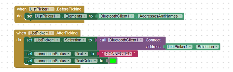
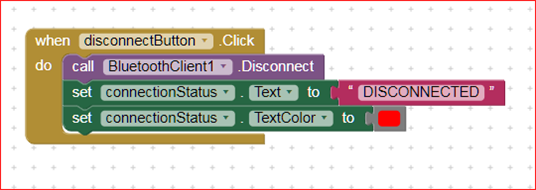
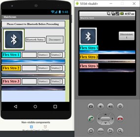
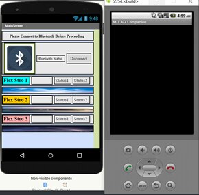
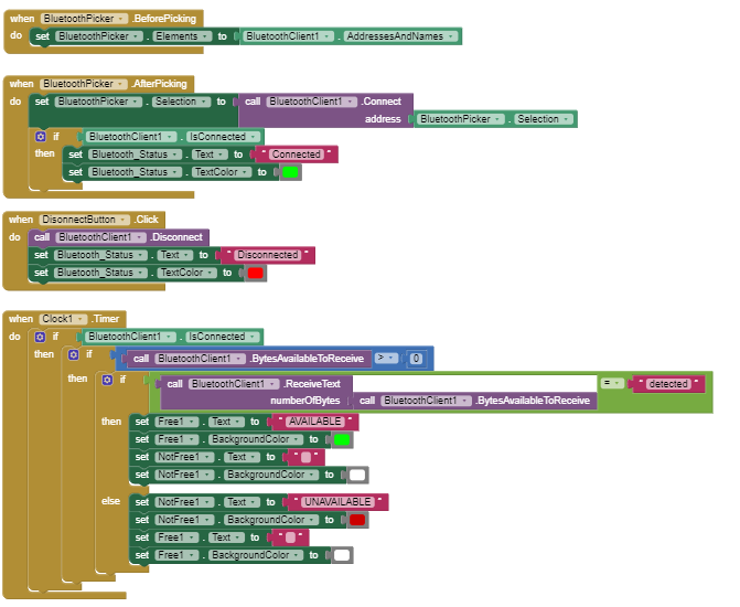
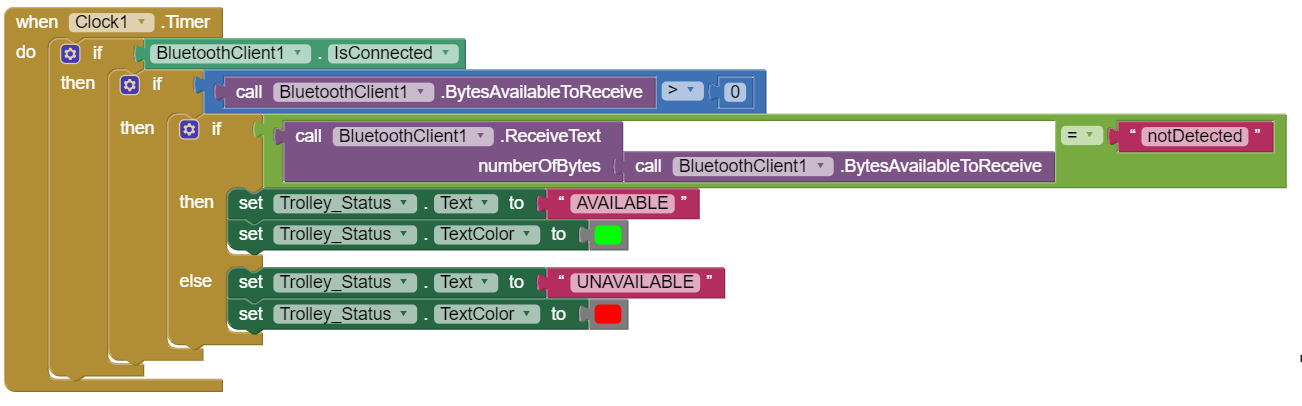
3. An App to receive the data which I created using MIT App Inventor

4. Door Magnetic Switch.


To be very honest I do not know where to start but I have already designed the User Interface of the Application without the Programming Block. I want it to work in away, when the Door Magnetic Switch formed closed circuit, it will send 1 or "ON" in the App through the Arduino Uno. However, when the Door Magnetic Switch formed an open circuit, it will send "0" of "OFF" in the App.


Is this possible?

Please help me. I am begging you. Please imageimage


  • Sign in to reply
  • Cancel

Top Replies

  • neilk
    neilk over 5 years ago in reply to kikovader +4 suggested
    Looking at your Arduino code, I can see that you are intending to connect the HC-05 Bluetooth module directly to the hardware Rx and Tx of the Arduino. Whilst this will work, it can be unreliable. It's…
  • neilk
    neilk over 5 years ago in reply to kikovader +4 verified
    Hi Kim Here is a slightly modified version of your Arduino Sketch: //Define the pins being used. //Connect the Door Magnetic Switch or Sensor to pin 4. // int ledOpen=2; int ledClose=3; int switchReed…
  • neilk
    neilk over 5 years ago in reply to kikovader +4 suggested
    You are welcome, Kim. Very pleased that it worked for you . You can't change the colour of the text you send from the Arduino to the App. You can, however, change the colour of the text displayed in the…
Parents
  • dougw
    0 dougw over 5 years ago

    The state can be changed in the UNO firmware or the App Inventor software with one or two lines of code or it can be changed in the hardware at the switch by altering how the magnetic switch is connected. Which method would you prefer?

    • Cancel
    • Vote Up 0 Vote Down
    • Sign in to reply
    • Verify Answer
    • Cancel
  • kikovader
    0 kikovader over 5 years ago in reply to dougw

    I am planning go display change of state in the MIT App Inventor Application which I built. In a way that, I want to use this App to monitor whether the door is close or open.

    I am just confused whether my codes in the Adruino IDE is correct and at the same I am also doubting my programming block in MIT App Inventor.

    Do you think it is possible to do this Sir?

    • Cancel
    • Vote Up 0 Vote Down
    • Sign in to reply
    • Verify Answer
    • Reject Answer
    • Cancel
  • dougw
    0 dougw over 5 years ago in reply to kikovader

    I expect if you post your code here, the members will provide advice.

    • Cancel
    • Vote Up 0 Vote Down
    • Sign in to reply
    • Verify Answer
    • Cancel
  • kikovader
    0 kikovader over 5 years ago in reply to dougw

    Hi Sir, I am sorry for the delay in replying to your help. But here is the code:


    //Define the pins being used.

    //Connect the Door Magnetic Switch or Sensor to pin 4.

    int ledOpen=2;

    int ledClose=3;

    int switchReed=4;


    //When the Door Magnetic Switch formed Closed Circuit = 1

    //When the Door Magnetic Swich formed Open Circuit = 0


    void setup()

    {

      //Initialize serial communication with Bluetooth Module HC-05


      Serial.begin(9600); //Serial.begin is used to set the speed of communication in bits per second. By default it is 9600. In short, changing the number will change the speed of transferring data.

      //Set the speed of transferring data to default speed.


      pinMode(ledOpen, OUTPUT);

      pinMode(ledClose, OUTPUT);

      pinMode(switchReed, INPUT);


    }


    void loop()

    {


      if (digitalRead(switchReed)==HIGH)

        {

          digitalWrite(ledOPen, LOW);

          digitalWrite(ledClose, HIGH);

          Serial.print("detected");

        }

      else

        {

          digitalWrite(ledOpen, HIGH);

          digitalWrite(ledClose, LOW);

          Serial.print(notDetected");

        }

        delay(100);

    }

    • Cancel
    • Vote Up +1 Vote Down
    • Sign in to reply
    • Verify Answer
    • Reject Answer
    • Cancel
  • Jan Cumps
    0 Jan Cumps over 5 years ago in reply to kikovader
    digitalWrite(ledOPen, LOW);


    You need to fix a typo in this line. Lower case P


    Serial.print(notDetected");


    Opening quotes missing.


    You could take care to only communicate if the status of the reedswitch changed between digital reads.

    • Cancel
    • Vote Up +2 Vote Down
    • Sign in to reply
    • Verify Answer
    • Reject Answer
    • Cancel
  • kikovader
    0 kikovader over 5 years ago in reply to kikovader

    Besides that, here is the User Interface for the App that I built.

    When the magnetic door switch formed a closed circuit, 1. I want "Status 2" of "Flex Stro 1" to display "Unavailable"

    When the magnetic door switch formed an open circuit, 0. I want "Status 1" of "Flex Stro 1" to display "Available"


    image


    image

    I am just unsure whether I have done it correctly and I have not tried this whole thing yet. But there is something inside me which tells me that it is wrong so yea.

    It would be nice if someone can help me out image

    • Cancel
    • Vote Up +2 Vote Down
    • Sign in to reply
    • Verify Answer
    • Reject Answer
    • Cancel
  • neilk
    0 neilk over 5 years ago in reply to kikovader

    Looking at your Arduino code, I can see that you are intending to connect the HC-05 Bluetooth module directly to the hardware Rx and Tx of the Arduino. Whilst this will work, it can be unreliable. It's much more reliable to use another pair of digital pins to communicate with your Bluetooth device. Have a look here at my blog:


    https://www.element14.com/community/people/neilk/blog/2018/02/14/mit-appinventor-and-arduino-much-improved-method-of-sending-data-from-arduino-and-receiving-on-android-device


    I have used HC-06, but it will also work with HC-05 - HC-06 is a slave only device. HC-05 can be programmed as a master or slave device. I think you could actually use HC-06 in your application.


    Your MIT AppInventor blocks don't include all that I have found necessary to connect to a Bluetooth device and don't contain any blocks to disconnect from the Bluetooth device.


    I always use a connection structure similar to this:


    image


    And I also include a disconnection block:


    image


    The rest of your blocks look OK, superficially, but I would always develop something as complex as this in small steps, testing each step as I go along. If you take this approach, you will be able to debug your project as you go along.


    Hope this helps


    Neil

    • Cancel
    • Vote Up +4 Vote Down
    • Sign in to reply
    • Verify Answer
    • Reject Answer
    • Cancel
Reply
  • neilk
    0 neilk over 5 years ago in reply to kikovader

    Looking at your Arduino code, I can see that you are intending to connect the HC-05 Bluetooth module directly to the hardware Rx and Tx of the Arduino. Whilst this will work, it can be unreliable. It's much more reliable to use another pair of digital pins to communicate with your Bluetooth device. Have a look here at my blog:


    https://www.element14.com/community/people/neilk/blog/2018/02/14/mit-appinventor-and-arduino-much-improved-method-of-sending-data-from-arduino-and-receiving-on-android-device


    I have used HC-06, but it will also work with HC-05 - HC-06 is a slave only device. HC-05 can be programmed as a master or slave device. I think you could actually use HC-06 in your application.


    Your MIT AppInventor blocks don't include all that I have found necessary to connect to a Bluetooth device and don't contain any blocks to disconnect from the Bluetooth device.


    I always use a connection structure similar to this:


    image


    And I also include a disconnection block:


    image


    The rest of your blocks look OK, superficially, but I would always develop something as complex as this in small steps, testing each step as I go along. If you take this approach, you will be able to debug your project as you go along.


    Hope this helps


    Neil

    • Cancel
    • Vote Up +4 Vote Down
    • Sign in to reply
    • Verify Answer
    • Reject Answer
    • Cancel
Children
  • kikovader
    0 kikovader over 5 years ago in reply to neilk

    Hi Neil,


    I am sorry if I took too long to reply to you but I have been trying to understand what are the differences if I connect my HC-05 to RX TX directly and what if I did not connect it directly.


    I tried to follow my original plan which is connecting the HC-05 to RX TX of the Arduino Directly, however faced some issues.


    I tried to use the MIT App Inventor Emulator to do the try out. At first it shows this:


    image

    When Bluetooth button was picked, the next screen shows nothing, basically it is just black and I do not know how this happen It does not even display the list of Bluetooth Connections available for me to connect. I did not download the App to my phone because I am using iOS L:(


    .image


    In terms of programming block, here is my programming block which I have modified according to your suggestion which is really makes sense:


    image


    And the programming code for the Arduino is below:

    //Define the pins being used.

    //Connect the Door Magnetic Switch or Sensor to pin 4.

    int ledOpen=2;

    int ledClose=3;

    int switchReed=4;


    //When the Door Magnetic Switch formed Closed Circuit = 1

    //When the Door Magnetic Swich formed Open Circuit = 0


    void setup()

    {

      //Initialize serial communication with Bluetooth Module HC-05


      Serial.begin(9600); //Serial.begin is used to set the speed of communication in bits per second. By default it is 9600. In short, changing the number will change the speed of transferring data.

      //Set the speed of transferring data to default speed.


      pinMode(ledOpen, OUTPUT);

      pinMode(ledClose, OUTPUT);

      pinMode(switchReed, INPUT);


    }


    void loop()

    {


      if (digitalRead(switchReed)==HIGH)

        {

          digitalWrite(ledOpen, LOW);

          digitalWrite(ledClose, HIGH);

          Serial.print("detected");

        }

      else

        {

          digitalWrite(ledOpen, HIGH);

          digitalWrite(ledClose, LOW);

          Serial.print("notDetected");

        }

        delay(100);

    }


    Could you help me to solve this issue image Please image

    • Cancel
    • Vote Up +1 Vote Down
    • Sign in to reply
    • Verify Answer
    • Reject Answer
    • Cancel
  • neilk
    0 neilk over 5 years ago in reply to kikovader

    Hi Kim


    Your set up is so complex (relatively speaking) that we cannot see the wood for the trees.


    Using the emulator doesn't help matters! It's much easier and more reliable to use the MIT AI2 Companion App on an Android device.


    I'm a bit confused as to your motivations in this project - using AppInventor when you don't have an Android device on which to run the App??


    So, why connecting the HC-05 directly to the Uno Rx and Tx, is unreliable:


    Firstly, the presence of the HC-05 across the Rx/Tx lines sometimes, but not always, stops a new sketch from being uploaded the the Uno. To rectify this it is necessary to disconnect the HC-05 from the Uno Rx/Tx


    Secondly,  the presence of the HC-05 across the Rx/Tx lines sometimes, but not always, stops the HC-05 from accepting a connection request on the Bluetooth side. To rectify this it is necessary to reset the HC-05, by disconnecting the +5V supply.


    So back to the project:


    You need to simplify your system so that it can be shown to work step by step. I suggest you do this by reproducing the stages in my blog which I referenced in my previous reply.


    If you cannot reproduce the steps in my Blog, then we need to delve deeper, and you will need to provide a schematic of the Uno and HC-05 connections.


    Until you can demonstrate that you can communicate with the Uno/HC-05 system, using something like Blueterm, there is little point in worrying about the detail of the AppInventor design and blocks.


    Hope this helps


    Neil

    • Cancel
    • Vote Up +2 Vote Down
    • Sign in to reply
    • Verify Answer
    • Reject Answer
    • Cancel
  • kikovader
    0 kikovader over 5 years ago in reply to neilk

    Hello Neil, I am extremely sorry for the delay in replying to your reply as I did not know why suddenly I could not log in to the e14 and I couldnt find my thread at all image. Little did I know, it was actually being reported as a spam image but it is okay as during that period of time I managed to solve the connecting issues. The current status is that, I managed to connect my HC-05 to an Android Phone. However, I faced another issue which is some instability in terms of transferring data. When the door magnetic switch forms 1 (when both are attracted to each other) the status which should be displayed in my app is supposed to be "AVAILABLE" and whe nthe door magnetic switch forms 0 (when the switch is not attracted to any magnet) the status which should be displayed in my app is supposed to be "UNAVAILABLE".

    The current status is that, when the door magnetic switch forms open circuit it satisfies the criteria which is in the app it displays "UNAVAILABLE".
    However, when the door magnetic switch forms closed circuit, the status keeps switching from "UNAVAIALBLE" to "AVAILABLE". I cannot receive "AVAILABLE" as the status as it keeps switching between the two status.


    In terms of connection.
    HC05 RX is connected to TX of Arduino (Pin 1)
    HC05 TX is connected to RX of Arduino (Pin 0)
    Door Magnetic Switch is connected to Pin 2 of Arduino.

    Both modules use common GND and common Vin.


    In terms of programming block I used in MIT App Inventor:
    image

    Here is a short video which shows the issue I am facing:
    image

    I hope to hear from you soon Sir. Cause I am just stressing over this thing right now. I have been stuck for quite sometimes (1 month) image

    • Cancel
    • Vote Up +3 Vote Down
    • Sign in to reply
    • Verify Answer
    • Reject Answer
    • Cancel
  • neilk
    0 neilk over 5 years ago in reply to kikovader

    Hi kikovader Sadly, your video is still encoding, so I am unable to watch it!


    However, now that you have a connection, you have been able to supply some information that shows up several problems:


    1. The Arduino code you posted your reply of November 13 has the Reed Switch connected to Arduino Pin 4; in your most recent reply, you say it is connected to pin 2
    2. Your Arduino code uses Serial.print to send either "detected" or "notDetected" to both the IDE serial monitor and the HC-05, simultaneously. You need to include a delimiter., otherwise the AppInventor Bluetooth block will almost certainly get confused! The AppInventor  block expects a default of Cr/Lf, so you should use Serial.println instead.
    3. You are checking the Reed Switch every 100 mS - delay(100); What time have you set the AppInventor Clock1 block to fire at? The default is 1 second, if you haven't changed it, then your AppInventor Bluetooth buffer will be flooded. You need to fire the AppInventor Clock1 slightly faster than the Arduino Loop - say 90 mS, to ensure that you read each message from the Arduino as soon as it is sent
    4. In AppInventor, you only check for "notDetected" and assume that if you didn't receive "notDetected", then you must have received "detected". In fact the way things are set up, you are receiving an almost continuous stream of text, containing no delimiters. What you actually read in AppInventor is a matter of luck!
    5. I'm pretty sure your Clock1 block could be simplified:  The second If: image

              Is almost certainly redundant and may well be contributing to your problem


    Not wishing to preach about step-wise development, but if you had actually stepped back and temporarily displayed within your User Inteface what you were actually capturing in AppInventor, then you might have better understood your problem. You would certainly have been able to provide more information here to help with diagnosing the problem.


    Hope this helps


    Neil

    • Cancel
    • Vote Up +1 Vote Down
    • Sign in to reply
    • Verify Answer
    • Reject Answer
    • Cancel
  • Jan Cumps
    0 Jan Cumps over 5 years ago in reply to neilk

    neilk  wrote:


    Hi kikovader  Sadly, your video is still encoding, so I am unable to watch it!


    ...

    The same for me. neilk, can you try to reload it?

    • Cancel
    • Vote Up +1 Vote Down
    • Sign in to reply
    • Verify Answer
    • Reject Answer
    • Cancel
  • kikovader
    0 kikovader over 5 years ago in reply to neilk

    Hi Neil, I am deeply sorry for the late reply again because I have been busy with examinations lately as I am still a student.

    I would like to reply to your bullet points.


    1. Initially, it was connected to pin 4 because I have connected pin 2 and 3 to LEDs just to check whether my Door Magnetic Switch is working perfectly by looking at the LED. When Door Magnetic Switch forms a closed circuit, LED connected to pin 3 will light up and when it forms an open circuit, LED connected to pin 2 will light up.


    2. I understand about this statement but I am still quite unsure on how to use a delimiter in Arduino IDE. I have been trying to research for some resources also but I did not find anything useful at all. Correct me if I am wrong, based on my past researches delimiter is basically to split a string or character?


    3. The delay I set in Arduino IDE was 100ms and just now I checked the MIT App Inventor for my clock interval it was measuring at 10ms. Do you think this might contribute the instability issue which I have currently?


    Just to keep everyone on the same page. The current problem I have right now is that in the Mobile Application which I built using MIT App Inventor it does not show stable results from Arduino Uno using HC05 Bluetooth Connection. I want the App to work under these two conditions:

    Condition 1: When Door Magnetic Switch forms a closed circuit (1), I want the App to display "Available"

    Condition 2: When Door Magnetic Switch forms an opened circuit (0), I want the App to display "Occupied"


    As of now, the App can fulfil Condition 2. However, when the Door Magnetic Switch forms a closed circuit (1), the App is unable to display a Fix "Available". It will keep displaying BOTH condition 2 and 1 at the same time when it forms a closed circuit. The app keeps switching its conditions within miliseconds. So it is not fix and stable. What might be the causes of this issue?


    I have tried to post the video also but I am unable to do so image


    I am sorry I am just a slow learner trying to learn coding sigh.

    • Cancel
    • Vote Up +2 Vote Down
    • Sign in to reply
    • Verify Answer
    • Reject Answer
    • Cancel
  • neilk
    0 neilk over 5 years ago in reply to kikovader

    Hi Kim


    Here is a slightly modified version of your Arduino Sketch:


    //Define the pins being used.
    //Connect the Door Magnetic Switch or Sensor to pin 4.
    //
    int ledOpen=2;
    int ledClose=3;
    int switchReed=4;
    
    
    //When the Door Magnetic Switch formed Closed Circuit = 1
    
    
    //When the Door Magnetic Swich formed Open Circuit = 0
    
    
    void setup()
    {
    //Initialize serial communication with Bluetooth Module HC-05
      Serial.begin(9600); //Serial.begin is used to set the speed of communication in bits per second. By default it is 9600. In short, changing the number will change the speed of transferring data.
      pinMode(ledOpen, OUTPUT);
      pinMode(ledClose, OUTPUT);
      pinMode(switchReed, INPUT);
    }
    void loop()
    {
      if (digitalRead(switchReed)==HIGH)
      {
        digitalWrite(ledOpen, LOW);
        digitalWrite(ledClose, HIGH);
        Serial.println("detected");       // Note use of Serial.println to send a newline after the string "detected" has been sent
      }
      else
      {
        digitalWrite(ledOpen, HIGH);
        digitalWrite(ledClose, LOW);
        Serial.println("notDetected");    // Note use of Serial.println to send a newline after the string "detected" has been sent
      }
        delay(1000);                      // 1 second delay between reads
    }


    I have also attached a very basic App Inventor app which should read data from the Arduino and display it on the screen of your Android device. You just need to import it into your AppInventor environment. It includes the design and the blocks.


    I say it SHOULD work, because I don't have an HC05 set up available for me to test it on!!


    Hope this helps


    Neil

    Attachments:
    Classic_BT_basic_data_from_Arduino.zip
    • Cancel
    • Vote Up +4 Vote Down
    • Sign in to reply
    • Verify Answer
    • Reject Answer
    • Cancel
  • kikovader
    0 kikovader over 5 years ago in reply to neilk

    HELLO NEILLLLLL!!!

    I AM SO HAPPY THAT WITH THE HELP OF YOUR PROGRAMMING BLOCKS FOR THE APP IT FINALLY WORKS OMG. THANKKKKK YOU SOOOO MUCH!!! image IS IT POSSIBLE FOR ME TO TREAT YOUR A CUP OF STARBUCKS COFFEEEEEE OMG HAHA. All i just need to do right now is trying to change the colour of the text sent to the app but I will figure it out myself. THANK YOU SO MUCH ONCE AGAIN OMG HAHAHAHA...


    Can I have your emailll I REALLY REALLY WANT TO TREAT YOUR STARBUCKS OMGGG!

    • Cancel
    • Vote Up +3 Vote Down
    • Sign in to reply
    • Verify Answer
    • Reject Answer
    • Cancel
  • neilk
    0 neilk over 5 years ago in reply to kikovader

    You are welcome, Kim. Very pleased that it worked for you image.


    You can't change the colour of the text you send from the Arduino to the App. You can, however, change the colour of the text displayed in the App with 2 simple blocks:


    image


    Good luck with the rest of your project


    Neil

    • Cancel
    • Vote Up +4 Vote Down
    • Sign in to reply
    • Verify Answer
    • Reject Answer
    • Cancel
  • kikovader
    0 kikovader over 5 years ago in reply to neilk

    Hi Neil, Its been long since we ever talked.

    Recently, I tried to test out the App using MIT App Inventor and the code using Arduino Uno Rev3.
    Though, I modified a few lines of the code, the issue which I had previously occur. The Bluetooth does not want to send information to the App which you built using MIT Inventor App.

    //Define the pins being used. 

    //Connect the Door Magnetic Switch or Sensor to pin 4. 


    #include <SoftwareSerial.h>

    SoftwareSerial mySerial (0, 1); //RX,TX

    int ledOpen=2; 

    int ledClose=3; 

    int switchReed=4; 


    //When the Door Magnetic Switch formed Closed Circuit = 1 


    //When the Door Magnetic Swich formed Open Circuit = 0 


    void setup() 

    { 

    //Initialize serial communication with Bluetooth Module HC-05 

      Serial.begin(9600); //Serial.begin is used to set the speed of communication in bits per second. By default it is 9600. In short, changing the number will change the speed of transferring data. 

      pinMode(ledOpen, OUTPUT); 

      pinMode(ledClose, OUTPUT); 

      pinMode(switchReed, INPUT); 

    } 

    void loop() 

    { 

      if (digitalRead(switchReed)==HIGH) 

      { 

        digitalWrite(ledOpen, LOW); 

        digitalWrite(ledClose, HIGH); 

        Serial.println("detected");       // Note use of Serial.println to send a newline after the string "detected" has been sent 

      } 

      else 

      { 

        digitalWrite(ledOpen, HIGH); 

        digitalWrite(ledClose, LOW); 

        Serial.println("notDetected");    // Note use of Serial.println to send a newline after the string "detected" has been sent 

      } 

        delay(1000);                      // 1 second delay between reads 

    }


    The underlined part is the new line which I added. Even though few months ago you adviced me not to use the RX/TX pins from the arduino uno.

    • Cancel
    • Vote Up +1 Vote Down
    • Sign in to reply
    • Verify Answer
    • Reject Answer
    • Cancel
element14 Community

element14 is the first online community specifically for engineers. Connect with your peers and get expert answers to your questions.

  • Members
  • Learn
  • Technologies
  • Challenges & Projects
  • Products
  • Store
  • About Us
  • Feedback & Support
  • FAQs
  • Terms of Use
  • Privacy Policy
  • Legal and Copyright Notices
  • Sitemap
  • Cookies

An Avnet Company © 2025 Premier Farnell Limited. All Rights Reserved.

Premier Farnell Ltd, registered in England and Wales (no 00876412), registered office: Farnell House, Forge Lane, Leeds LS12 2NE.

ICP 备案号 10220084.

Follow element14

  • X
  • Facebook
  • linkedin
  • YouTube