element14 Community
element14 Community
    Register Log In
  • Site
  • Search
  • Log In Register
  • Community Hub
    Community Hub
    • What's New on element14
    • Feedback and Support
    • Benefits of Membership
    • Personal Blogs
    • Members Area
    • Achievement Levels
  • Learn
    Learn
    • Ask an Expert
    • eBooks
    • element14 presents
    • Learning Center
    • Tech Spotlight
    • STEM Academy
    • Webinars, Training and Events
    • Learning Groups
  • Technologies
    Technologies
    • 3D Printing
    • FPGA
    • Industrial Automation
    • Internet of Things
    • Power & Energy
    • Sensors
    • Technology Groups
  • Challenges & Projects
    Challenges & Projects
    • Design Challenges
    • element14 presents Projects
    • Project14
    • Arduino Projects
    • Raspberry Pi Projects
    • Project Groups
  • Products
    Products
    • Arduino
    • Avnet & Tria Boards Community
    • Dev Tools
    • Manufacturers
    • Multicomp Pro
    • Product Groups
    • Raspberry Pi
    • RoadTests & Reviews
  • About Us
    About the element14 Community
  • Store
    Store
    • Visit Your Store
    • Choose another store...
      • Europe
      •  Austria (German)
      •  Belgium (Dutch, French)
      •  Bulgaria (Bulgarian)
      •  Czech Republic (Czech)
      •  Denmark (Danish)
      •  Estonia (Estonian)
      •  Finland (Finnish)
      •  France (French)
      •  Germany (German)
      •  Hungary (Hungarian)
      •  Ireland
      •  Israel
      •  Italy (Italian)
      •  Latvia (Latvian)
      •  
      •  Lithuania (Lithuanian)
      •  Netherlands (Dutch)
      •  Norway (Norwegian)
      •  Poland (Polish)
      •  Portugal (Portuguese)
      •  Romania (Romanian)
      •  Russia (Russian)
      •  Slovakia (Slovak)
      •  Slovenia (Slovenian)
      •  Spain (Spanish)
      •  Sweden (Swedish)
      •  Switzerland(German, French)
      •  Turkey (Turkish)
      •  United Kingdom
      • Asia Pacific
      •  Australia
      •  China
      •  Hong Kong
      •  India
      •  Japan
      •  Korea (Korean)
      •  Malaysia
      •  New Zealand
      •  Philippines
      •  Singapore
      •  Taiwan
      •  Thailand (Thai)
      •  Vietnam
      • Americas
      •  Brazil (Portuguese)
      •  Canada
      •  Mexico (Spanish)
      •  United States
      Can't find the country/region you're looking for? Visit our export site or find a local distributor.
  • Translate
  • Profile
  • Settings
Arduino
  • Products
  • More
Arduino
Arduino Forum Linear Pot to control a servo how to adjust the travel of the dial from left to right
  • Blog
  • Forum
  • Documents
  • Quiz
  • Events
  • Polls
  • Files
  • Members
  • Mentions
  • Sub-Groups
  • Tags
  • More
  • Cancel
  • New
Join Arduino to participate - click to join for free!
Actions
  • Share
  • More
  • Cancel
Forum Thread Details
  • State Not Answered
  • Replies 17 replies
  • Subscribers 411 subscribers
  • Views 2424 views
  • Users 0 members are here
  • linear
  • arduino_uno
  • pot
  • servo_motor_control
Related

Linear Pot to control a servo how to adjust the travel of the dial from left to right

Former Member
Former Member over 12 years ago

Hello....

My supplies:

Arduino UNO

TowerPro Servo

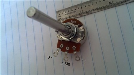
Linear Pot. (radio shack 271-1715 ( http://www.radioshack.com/product/index.jsp?productId=2062354#inTheBox ))

Sketch being used: Arduino / File / Example / Servos / Knob

*******************************************

Ok hope the supplies help you, help me image


Everything works wonderful using this example, but my question is:

The lineear pot turns from left to right about, maybe 350°, in laymen terms picture a clock 7 being the start, 5 being the stop.

The servo will turn, when the pot is turned, but it seems as though the servo does NOT star moving until (using the example above until 11, and completes its travels upto 1) sorry for using this as an example, but its the best way to paint the picture.

So can someone tell me what I need to do in order to get the servo to start turning say around 8 and stop right around say 4?

here is the code if you are unfamiliar with it:

// Controlling a servo position using a potentiometer (variable resistor)
// by Michal Rinott <http://people.interaction-ivrea.it/m.rinott>

#include <Servo.h>

Servo myservo;  // create servo object to control a servo

int potpin = 0;  // analog pin used to connect the potentiometer
int val;    // variable to read the value from the analog pin

void setup()
{
  myservo.attach(9);  // attaches the servo on pin 9 to the servo object
}

void loop()
{
  val = analogRead(potpin);            // reads the value of the potentiometer (value between 0 and 1023)
  val = map(val, 0, 1023, 0, 179);     // scale it to use it with the servo (value between 0 and 180)
  myservo.write(val);                  // sets the servo position according to the scaled value
  delay(15);                           // waits for the servo to get there
}


Thanks for your help...

Tony

  • Sign in to reply
  • Cancel

Top Replies

  • billabott
    billabott over 12 years ago in reply to Former Member +1
    Wanna be an EE? Then I recommend you use quadrille paper for the photos next time. That goes for everyone.
  • mcb1
    mcb1 over 12 years ago in reply to billabott +1
    The other option would be to output each of the ADC readings at every hour position. This would then give some figures to set the servo output to. The code is straight from the example on the arduino site…
  • mcb1
    mcb1 over 12 years ago in reply to billabott +1
    Funny while looking at the other servo issue, I had the same idea.... You can specify the max and min pwm values, and this may be a way of overcoming the problem. You'll need to either find someones elses…
  • billabott
    0 billabott over 12 years ago

    Change

          val = map(val, 0, 1023, 0, 179);

    to

          val = map(val, 0, 1023, 50, 129);

    or

          val = map(val, 0, 1023, 70, 109);


    • Cancel
    • Vote Up 0 Vote Down
    • Sign in to reply
    • Verify Answer
    • Cancel
  • Former Member
    0 Former Member over 12 years ago in reply to billabott

    Bill - Hi

    In doing both of your changes, the servo (which is just a 180 degree hobby servo) is not reacting to the contral pot as desired.

    If I may, can you advise me, should I require these in microseconds?


    Tony

    • Cancel
    • Vote Up 0 Vote Down
    • Sign in to reply
    • Verify Answer
    • Cancel
  • billabott
    0 billabott over 12 years ago in reply to Former Member

    Dear Tony,

       What is the only other possible option?

    change

       val = map(val, 0, 1023, 0, 179);

    to

       val = map(val, 300, 723, 0, 179);


    Give it a shot and provide some feedback.  thanks.

    • Cancel
    • Vote Up 0 Vote Down
    • Sign in to reply
    • Verify Answer
    • Cancel
  • Former Member
    0 Former Member over 12 years ago in reply to billabott

    unfortantely its still not working..In a nutshell,...I want to be able to use the entire stroke of the dial;  When its all the way to the left, the servo should be at zero, when I turn it all the way to the right, the servo should be at the 180 degree mark (well 179 actually)  I need to get the pot, very very sensative I guess, in order to make it a smooth ride..I would even be satisfied with about 5 degrees at a time while turn the dial.


    Tony

    • Cancel
    • Vote Up 0 Vote Down
    • Sign in to reply
    • Verify Answer
    • Cancel
  • billabott
    0 billabott over 12 years ago in reply to Former Member

    Terribly sorry, Old Chap.  Have you visited adafruit.com and sparkfun.com for tutorials and other info?  Then there is the official arduino.cc.  They have a wonderful tutorial to be found here: http://playground.arduino.cc/Learning/SingleServoExample  Then there is pololu.com and oomlout.com.  You may even wish to visit letsmakerobots.com.


    I am having trouble believing that the potentiometer is linear.  Maybe it is a logrithmic audio pot.

    http://sound.westhost.com/pots.htm


    Confirm the following setup: the UNO's analog pin 0 is connected to the wiper of the pot and the low side of the pot is connected to ground AND the high side of the pot is connected to 5 volts.  Use a multimeter to confirm the value of the pot at 12 o'clock is 5K ohm on  both the low and high pins of the pot with respect to the wiper.


    Give a full specification of the servo with link to data sheet.  I am willing to bet it is a SG90.  Someone else had one of those and it was nothing but problems.  He had to go buy a normal servo and it then worked fine.

    • Cancel
    • Vote Up 0 Vote Down
    • Sign in to reply
    • Verify Answer
    • Cancel
  • billabott
    0 billabott over 12 years ago

    Do you have any idea what the following means?


    Operating Speed (4.8V no load): 0.12sec/60 degrees


    0.120 seconds = 120 ms (milleseconds)


    The 12 ms your delay() is using is not adequate, a bare minimum would be some where between 360 ms and 100 ms.

    • Cancel
    • Vote Up 0 Vote Down
    • Sign in to reply
    • Verify Answer
    • Cancel
  • Former Member
    0 Former Member over 12 years ago in reply to billabott

    In response to billabbott from #5 comment:


    Hi Bill,

    No believe it, it is a linear pot.  Link to the actual ones purchased: http://www.radioshack.com/product/index.jsp?productId=2062354#inTheBox


    The audio’s are: http://www.radioshack.com/product/index.jsp?productId=2062357&filterName=Type&filterValue=Potentiometers


    Although they are identical builds, it is my understanding that the audio board is setup differently.  The board on this one is B10K (see pic below) as per the link you provided http://sound.westhost.com/pots.htm


    Confirmation of the setup is that the UNO anolog pin is 0 (or A0) and is connected to the center pin on the pot (referred to as 2 Sig in attached pic)


    There servo datasheet: is attached as a pdf http://www.kbaam.com/servo/servo.htm


    Attached is an actual pic of the servo sitting on my notebook.

    imageimage

    Tony

    • Cancel
    • Vote Up 0 Vote Down
    • Sign in to reply
    • Verify Answer
    • Cancel
  • Former Member
    0 Former Member over 12 years ago in reply to billabott

    In response to billabbott from #6 comment:

    Do you have any idea what the following means?


    Operating Speed (4.8V no load): 0.12sec/60 degrees <-- I believe this means at 4.8 volts with no load it will take the servo 0.12sec to turn 60° from its starting point.  Which means that I would need to take into account the weight I am trying to move with the servo - that answer is approximately 00.6 ounces (17.01 grams)


    The 12 ms your delay() is using is not adequate, a bare minimum would be some where between 360 ms and 100 ms. <--- I agree with you that the 12 ms delay is not adequate, but there was no servo hooked up at this time.  I was doing readings from the serial monitor.  But I did perform the following test per your suggestion. 


    My multimeter registered the following:


    With the + probe on pin 1+ (see pic above), and - probe on 2 Sig. (Signal see pic) I registered the following volts:

    Complete left or what I refer to as 7 o'clock, I registered 4.4 volts, as I turned the dial / knob towards the right, to 12 o'clock, the volts dropped down 2.4 volts (thats a good thing) and to complete the travel all the way to 4 o'clock it registered 0 volts.


    Now with keeping the - probe on the 2 Sig, and moving the + probe to 3-, I received the following:

    Complete left or what I refer to as 7 o'clock, I registered 0.0 volts, as I turned the dial / knob towards the right, to 12 o'clock, the volts dropped increased to 2.0 volts (thats a good thing) and to complete the travel all the way to 4 o'clock it registered 4.3 volts.


    Hope that helped you

    Tony

    • Cancel
    • Vote Up 0 Vote Down
    • Sign in to reply
    • Verify Answer
    • Cancel
  • billabott
    0 billabott over 12 years ago in reply to Former Member

    Thank for sharing your test results.  Your report does remove most of the doubt about it not being a linear pot. I am no expert with regards to servo motors. I do like to think that this experience helping you will challenge me, the co-learner, to sort it out and advance my knowledge.  There is only one case that I can think of that fits the reported data.  And that can be tested with the multimeter's ohmmeter mode.  Please recall that what you wanted originally was an explanation as to why the pot servo was not moving unless the pot knob was between 11 and 1 o'clock positions.  We are trying to get to that with the following experiment:


    With NO application of power to the pot (remove it from the circuit); put the ohmmeter probes on pins 1 an 2 of the pot and record the measured resistance at every o'clock position from 7 to 4.  That is every 30 degrees. Then do it again with pins 2 and 3 (results will be reversed).  In a perfect world it would go 0K, 1K, 2K, 3K, 4K, 5K, 6K, 7K, 8K, 9K, 10K ohms.    Please report back with the results.


    There is an arduino sketch at http://learn.adafruit.com/adafruit-arduino-lesson-14-servo-motors where by you can certify the correct funtion of your servo if you want to try it.


    Don't miss this part of that tutorial: http://learn.adafruit.com/adafruit-arduino-lesson-14-servo-motors/if-the-servo-misbehaves.

    • Cancel
    • Vote Up 0 Vote Down
    • Sign in to reply
    • Verify Answer
    • Cancel
  • billabott
    0 billabott over 12 years ago in reply to Former Member

    Wanna be an EE?  Then I recommend you use quadrille paper for the photos next time. 


    image That goes for everyone. image

    • Cancel
    • Vote Up +1 Vote Down
    • Sign in to reply
    • Verify Answer
    • Cancel
>
element14 Community

element14 is the first online community specifically for engineers. Connect with your peers and get expert answers to your questions.

  • Members
  • Learn
  • Technologies
  • Challenges & Projects
  • Products
  • Store
  • About Us
  • Feedback & Support
  • FAQs
  • Terms of Use
  • Privacy Policy
  • Legal and Copyright Notices
  • Sitemap
  • Cookies

An Avnet Company © 2026 Premier Farnell Limited. All Rights Reserved.

Premier Farnell Ltd, registered in England and Wales (no 00876412), registered office: Farnell House, Forge Lane, Leeds LS12 2NE.

ICP 备案号 10220084.

Follow element14

  • X
  • Facebook
  • linkedin
  • YouTube