element14 Community
element14 Community
    Register Log In
  • Site
  • Search
  • Log In Register
  • Community Hub
    Community Hub
    • What's New on element14
    • Feedback and Support
    • Benefits of Membership
    • Personal Blogs
    • Members Area
    • Achievement Levels
  • Learn
    Learn
    • Ask an Expert
    • eBooks
    • element14 presents
    • Learning Center
    • Tech Spotlight
    • STEM Academy
    • Webinars, Training and Events
    • Learning Groups
  • Technologies
    Technologies
    • 3D Printing
    • FPGA
    • Industrial Automation
    • Internet of Things
    • Power & Energy
    • Sensors
    • Technology Groups
  • Challenges & Projects
    Challenges & Projects
    • Design Challenges
    • element14 presents Projects
    • Project14
    • Arduino Projects
    • Raspberry Pi Projects
    • Project Groups
  • Products
    Products
    • Arduino
    • Avnet & Tria Boards Community
    • Dev Tools
    • Manufacturers
    • Multicomp Pro
    • Product Groups
    • Raspberry Pi
    • RoadTests & Reviews
  • About Us
    About the element14 Community
  • Store
    Store
    • Visit Your Store
    • Choose another store...
      • Europe
      •  Austria (German)
      •  Belgium (Dutch, French)
      •  Bulgaria (Bulgarian)
      •  Czech Republic (Czech)
      •  Denmark (Danish)
      •  Estonia (Estonian)
      •  Finland (Finnish)
      •  France (French)
      •  Germany (German)
      •  Hungary (Hungarian)
      •  Ireland
      •  Israel
      •  Italy (Italian)
      •  Latvia (Latvian)
      •  
      •  Lithuania (Lithuanian)
      •  Netherlands (Dutch)
      •  Norway (Norwegian)
      •  Poland (Polish)
      •  Portugal (Portuguese)
      •  Romania (Romanian)
      •  Russia (Russian)
      •  Slovakia (Slovak)
      •  Slovenia (Slovenian)
      •  Spain (Spanish)
      •  Sweden (Swedish)
      •  Switzerland(German, French)
      •  Turkey (Turkish)
      •  United Kingdom
      • Asia Pacific
      •  Australia
      •  China
      •  Hong Kong
      •  India
      •  Japan
      •  Korea (Korean)
      •  Malaysia
      •  New Zealand
      •  Philippines
      •  Singapore
      •  Taiwan
      •  Thailand (Thai)
      •  Vietnam
      • Americas
      •  Brazil (Portuguese)
      •  Canada
      •  Mexico (Spanish)
      •  United States
      Can't find the country/region you're looking for? Visit our export site or find a local distributor.
  • Translate
  • Profile
  • Settings
Arduino
  • Products
  • More
Arduino
Arduino Forum Simple circuiting question, using Arduino
  • Blog
  • Forum
  • Documents
  • Quiz
  • Events
  • Polls
  • Files
  • Members
  • Mentions
  • Sub-Groups
  • Tags
  • More
  • Cancel
  • New
Join Arduino to participate - click to join for free!
Actions
  • Share
  • More
  • Cancel
Forum Thread Details
  • State Verified Answer
  • Replies 30 replies
  • Answers 2 answers
  • Subscribers 420 subscribers
  • Views 3171 views
  • Users 0 members are here
Related

Simple circuiting question, using Arduino

e14 Contributor
e14 Contributor over 13 years ago

I want to control a 24v DC circuit with a my arduino, what would be the proper component and roughly how would I use it. Basically when I set a pin to high, I want it to switch the 24V on, and turn it off when set to low. From what I can gather, I need a MOSFET, but I have minimal knowledge on what to look for in one. Would someone be able to assist me?


(p.s. This is my first discussion, sorry if I am doing this incorrectly)

  • Sign in to reply
  • Cancel

Top Replies

  • johnbeetem
    johnbeetem over 13 years ago in reply to ntewinkel +2
    Nico teWinkel wrote: You should probably at least have a resistor between the Arduino pin and the mosfet. [I've never designed with Arduino, so these are comments that apply to most microcontrollers.]…
  • ntewinkel
    ntewinkel over 13 years ago +1 suggested
    Hi Mason, You should probably at least have a resistor between the Arduino pin and the mosfet. Oomlout has a circuit example using a smaller transistor: http://www.oomlout.com/oom.php/products/ardx/circ…
  • ntewinkel
    ntewinkel over 13 years ago +1
    ps, this Instructable might also help: http://www.instructables.com/id/Use-Arduino-with-TIP120-transistor-to-control-moto/
  • billpenner
    0 billpenner over 13 years ago

    Just a couple of thoughts..

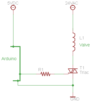
    The Valve is a 24Volt AC device. Some times this will work on DC and some times it won't. The reason is that an AC device depends upon the Impedance (AC resistance) to limit the current through the circuit, while only the DC resistance of the wire limits the current when DC is applied. I hope this makes sense. The bottom line is that if you use DC to operate an AC device it will draw more current, overheat and probably burn out.

    I suggest that you us a Triac to operate the water valve using 24VAC. You can control the Triac using a resistor fron the gate of the triac to Arduino.

    The resistor should be selectde based on the Triac trigger current.


    Sorry the Schematis is Large. Thisn is the first schematic I have created for Element14.

    (Help would be appreciated in this area)

    Bill

    image

    • Cancel
    • Vote Up 0 Vote Down
    • Sign in to reply
    • Verify Answer
    • Cancel
  • johnbeetem
    0 johnbeetem over 13 years ago in reply to e14 Contributor

    Mason Adkins wrote:


    John,

    Thanks a lot for the info, this seems like a better system. Would you be able to skim this and confirm is what you are suggesting?

    http://www.youtube.com/watch?v=1Q0ZwpycbzY


    If so, would I be able to safely switch the 6v input he uses, for my 24v source?

    Sure, that looks good.  According to the ST data sheet, the L298 can switch up to 46V, so 24V leaves plenty of margin.  I noticed that the video did not have flyback diodes on the outputs.  I guess with such a small motor they weren't needed, but the data sheet does recommend them and shows where they go.  The problem with motors, relays, and any inductive load is that once you get a current going through an inductor it doesn't want to stop.  So if you switch it off, the current keeps flowing as the magnetic field collapses and if the current can't go anywhere it charges whatever stray capacitance is on the node creating a high voltage spike.  This is similar to how spark plugs work.  The diodes provide a current path to prevent the spikes, which can destroy transistors.


    You might be able to get a module that already has the diodes built in, or there may be better chips available.


    As I said earlier, use LEDs and suitable current limiting resistors to verify operation before hooking up to the real world device.

    • Cancel
    • Vote Up 0 Vote Down
    • Sign in to reply
    • Verify Answer
    • Cancel
  • e14 Contributor
    0 e14 Contributor over 13 years ago in reply to johnbeetem

    Awesome, thanks again.


    Everyone here is so helpfull, great community. I will be back when I have more questions!

    • Cancel
    • Vote Up 0 Vote Down
    • Sign in to reply
    • Verify Answer
    • Cancel
  • johnbeetem
    0 johnbeetem over 13 years ago in reply to billpenner

    billpenner wrote:


    Just a couple of thoughts..

    The Valve is a 24Volt AC device.

    Ah... I was wondering if it was AC.  In that case, I'd use a small 5V DC relay to switch the 24V AC on and off.  That way the Arduino is isolated from the 24V circuit and you can just use a transistor or Darlington pair to drive the relay coil through a resistor.

    • Cancel
    • Vote Up 0 Vote Down
    • Sign in to reply
    • Verify Answer
    • Cancel
  • billpenner
    0 billpenner over 13 years ago in reply to johnbeetem

    The Triac is simple, cheap and reliable. as a mater of fact the controllers for the valves use triacs for driving the valves. However, ghe relay will work just fine if the relay coil doesn't draw more current than the Arduino can supply. good luck

    Bill


    PS: If you use a transistor to drive the relay, you will need to also add a diode to protect the transistor against spikes from the coil.

    • Cancel
    • Vote Up +1 Vote Down
    • Sign in to reply
    • Verify Answer
    • Cancel
  • mcb1
    0 mcb1 over 13 years ago in reply to billpenner

    I personally would NOT drive the triac that way.


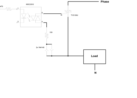
    I would use an optocoupler which then feeds the gate of the triac.


    The cct below was used for driving rather inductive loads from 230 or 24v AC, so it will handle the water valve just fine.

    We used that particular Triac because they are 10A and isolated heatsink, meaning you could earth or ground it without using any insulating bushes, etc.


    image


    Mason

    Your MJE3055 has a fairly low gain of 20-70 (the sheet I looked at from ST)

    That is the say you need to feed the base with 1/20th or 1/70th of the current the water valve draws.

    If the valve draws 4A (4000mA) then at a gain of 20, you need to provide 200mA into the base.


    Generally a TIP120 darlington transistor will have a gain of 1000, hence you would only need 4mA.


    Mark

    • Cancel
    • Vote Up +1 Vote Down
    • Sign in to reply
    • Verify Answer
    • Cancel
  • billpenner
    0 billpenner over 13 years ago in reply to mcb1

    Thanks for your comment.  But may I say that the increased number of parts and complexity of adding the optpcoupler might not be justified in this case.

    I have used many AC line circuit designed with an optocoupler which is definitely required when working with an AC line. in this case however the 24 volts will be isolated from the line already via a transformer so no isolation is needed

    .

    If by some strange and unusual circumstance the 24 volts is not isolated from the line then you are absolutely correct.


    If  Mark elects to use a 2N6071 sensitive gate Triac then he would need to use a 510 Ohm resistor to drive the gate. This Triac will handle 4 Amp and 200 Volts which is plenty for your circuit. The gate drive is only 5 mA.The cost is less than a buck.


    I hope this helps.

    Bill

    • Cancel
    • Vote Up 0 Vote Down
    • Sign in to reply
    • Verify Answer
    • Cancel
  • mcb1
    0 mcb1 over 13 years ago in reply to billpenner

    billpenner wrote:

    If by some strange and unusual circumstance the 24 volts is not isolated from the line then you are absolutely correct.


    Bill quite right you can happily have 24v AC tied to the heatsink.

    It's when someone decides that 'Mains' voltage is also okay its a problem....especially if they also make the case the heatsink.


    We started using that configuration when we were having trouble with the inductive loads causing the triacs to misfire and stay partially on.

    I normally prefer to switch grounds, but with 230v AC the electricians get confused ...


    Re the extra parts.

    Yes there are some, and if you were going into mass manufacture you might hesitate, but it also means any triac pin confusion/wiring issues don't result in 24v AC up the input of the Arduino....


    Mark

    • Cancel
    • Vote Up 0 Vote Down
    • Sign in to reply
    • Verify Answer
    • Cancel
  • e14 Contributor
    0 e14 Contributor over 13 years ago

    Haha, you guys have lost me with all ths talk of AC. I have definitely seen instances of this valve being run off of DC, so I am pretty confident using this h-bridge chip should do.

    • Cancel
    • Vote Up 0 Vote Down
    • Sign in to reply
    • Verify Answer
    • Cancel
  • billpenner
    0 billpenner over 13 years ago in reply to e14 Contributor

    Mason; Please accept my appologies for all my answers and comments re: Simple....

    I assumed way too much. I invfestagated as much as I could via internet on the your actual valve. It turns out I was using my previous experience with Orbit valves and controllers. It appears that the valve is a DC valve using batteries contained in the conrroller. If true, we have confussed the whole issue. Please confirm if the controller connects to  rhe AC line via a transformer. If not, disregard this total discussion. I will confirm my next visit to Home Depot. If the valve is indeed operated by the DC controller then YES you can controll the valve(s) with the Arduino using a small transistor and a diode. Either a FET or a bipolar transistor can be used. Very simple!. Again very sorry to lead you astray.

    Bill

    • Cancel
    • Vote Up 0 Vote Down
    • Sign in to reply
    • Verify Answer
    • Cancel
<
element14 Community

element14 is the first online community specifically for engineers. Connect with your peers and get expert answers to your questions.

  • Members
  • Learn
  • Technologies
  • Challenges & Projects
  • Products
  • Store
  • About Us
  • Feedback & Support
  • FAQs
  • Terms of Use
  • Privacy Policy
  • Legal and Copyright Notices
  • Sitemap
  • Cookies

An Avnet Company © 2026 Premier Farnell Limited. All Rights Reserved.

Premier Farnell Ltd, registered in England and Wales (no 00876412), registered office: Farnell House, Forge Lane, Leeds LS12 2NE.

Follow element14

  • X
  • Facebook
  • linkedin
  • YouTube