element14 Community
element14 Community
    Register Log In
  • Site
  • Search
  • Log In Register
  • Community Hub
    Community Hub
    • What's New on element14
    • Feedback and Support
    • Benefits of Membership
    • Personal Blogs
    • Members Area
    • Achievement Levels
  • Learn
    Learn
    • Ask an Expert
    • eBooks
    • element14 presents
    • Learning Center
    • Tech Spotlight
    • STEM Academy
    • Webinars, Training and Events
    • Learning Groups
  • Technologies
    Technologies
    • 3D Printing
    • FPGA
    • Industrial Automation
    • Internet of Things
    • Power & Energy
    • Sensors
    • Technology Groups
  • Challenges & Projects
    Challenges & Projects
    • Design Challenges
    • element14 presents Projects
    • Project14
    • Arduino Projects
    • Raspberry Pi Projects
    • Project Groups
  • Products
    Products
    • Arduino
    • Avnet & Tria Boards Community
    • Dev Tools
    • Manufacturers
    • Multicomp Pro
    • Product Groups
    • Raspberry Pi
    • RoadTests & Reviews
  • About Us
    About the element14 Community
  • Store
    Store
    • Visit Your Store
    • Choose another store...
      • Europe
      •  Austria (German)
      •  Belgium (Dutch, French)
      •  Bulgaria (Bulgarian)
      •  Czech Republic (Czech)
      •  Denmark (Danish)
      •  Estonia (Estonian)
      •  Finland (Finnish)
      •  France (French)
      •  Germany (German)
      •  Hungary (Hungarian)
      •  Ireland
      •  Israel
      •  Italy (Italian)
      •  Latvia (Latvian)
      •  
      •  Lithuania (Lithuanian)
      •  Netherlands (Dutch)
      •  Norway (Norwegian)
      •  Poland (Polish)
      •  Portugal (Portuguese)
      •  Romania (Romanian)
      •  Russia (Russian)
      •  Slovakia (Slovak)
      •  Slovenia (Slovenian)
      •  Spain (Spanish)
      •  Sweden (Swedish)
      •  Switzerland(German, French)
      •  Turkey (Turkish)
      •  United Kingdom
      • Asia Pacific
      •  Australia
      •  China
      •  Hong Kong
      •  India
      •  Japan
      •  Korea (Korean)
      •  Malaysia
      •  New Zealand
      •  Philippines
      •  Singapore
      •  Taiwan
      •  Thailand (Thai)
      •  Vietnam
      • Americas
      •  Brazil (Portuguese)
      •  Canada
      •  Mexico (Spanish)
      •  United States
      Can't find the country/region you're looking for? Visit our export site or find a local distributor.
  • Translate
  • Profile
  • Settings
Arduino
  • Products
  • More
Arduino
Arduino Forum Simple circuiting question, using Arduino
  • Blog
  • Forum
  • Documents
  • Quiz
  • Events
  • Polls
  • Files
  • Members
  • Mentions
  • Sub-Groups
  • Tags
  • More
  • Cancel
  • New
Join Arduino to participate - click to join for free!
Actions
  • Share
  • More
  • Cancel
Forum Thread Details
  • State Verified Answer
  • Replies 30 replies
  • Answers 2 answers
  • Subscribers 420 subscribers
  • Views 3151 views
  • Users 0 members are here
Related

Simple circuiting question, using Arduino

e14 Contributor
e14 Contributor over 13 years ago

I want to control a 24v DC circuit with a my arduino, what would be the proper component and roughly how would I use it. Basically when I set a pin to high, I want it to switch the 24V on, and turn it off when set to low. From what I can gather, I need a MOSFET, but I have minimal knowledge on what to look for in one. Would someone be able to assist me?


(p.s. This is my first discussion, sorry if I am doing this incorrectly)

  • Sign in to reply
  • Cancel

Top Replies

  • johnbeetem
    johnbeetem over 13 years ago in reply to ntewinkel +2
    Nico teWinkel wrote: You should probably at least have a resistor between the Arduino pin and the mosfet. [I've never designed with Arduino, so these are comments that apply to most microcontrollers.]…
  • ntewinkel
    ntewinkel over 13 years ago +1 suggested
    Hi Mason, You should probably at least have a resistor between the Arduino pin and the mosfet. Oomlout has a circuit example using a smaller transistor: http://www.oomlout.com/oom.php/products/ardx/circ…
  • ntewinkel
    ntewinkel over 13 years ago +1
    ps, this Instructable might also help: http://www.instructables.com/id/Use-Arduino-with-TIP120-transistor-to-control-moto/
  • e14 Contributor
    0 e14 Contributor over 13 years ago

    Upon further reasearch, I have found out that I could use a simple N type MOSFET, and apply the Arduino pin output the the gate. Is there anything I need to do to protect my Arduino board?

    • Cancel
    • Vote Up 0 Vote Down
    • Sign in to reply
    • Verify Answer
    • Cancel
  • ntewinkel
    0 ntewinkel over 13 years ago

    Hi Mason,


    You should probably at least have a resistor between the Arduino pin and the mosfet.


    Oomlout has a circuit example using a smaller transistor: http://www.oomlout.com/oom.php/products/ardx/circ-03


    Not sure if in your case you might also want an optocoupler (http://en.wikipedia.org/wiki/Opto-isolator) because of the difference in voltage.


    Cheers,

    -Nico

    • Cancel
    • Vote Up +1 Vote Down
    • Sign in to reply
    • Verify Answer
    • Reject Answer
    • Cancel
  • ntewinkel
    0 ntewinkel over 13 years ago

    ps, this Instructable might also help: http://www.instructables.com/id/Use-Arduino-with-TIP120-transistor-to-control-moto/

    • Cancel
    • Vote Up +1 Vote Down
    • Sign in to reply
    • Verify Answer
    • Cancel
  • johnbeetem
    0 johnbeetem over 13 years ago in reply to ntewinkel

    Nico teWinkel wrote:


    You should probably at least have a resistor between the Arduino pin and the mosfet.

    [I've never designed with Arduino, so these are comments that apply to most microcontrollers.]


    I agree with this.  You need to protect the Arduino in the unlikely event that the NFET shorts between gate and source and presents 24V to the Arduino pin.  I would guess that the Arduino has internal clamping diodes to prevent pins from going too high, but those burn out at high currents.  So having a resistor (I usually start with 1K) controls the amount of current so that the clamp doesn't burn out.


    With an NFET, you also need to be concerned with what happens at power on.  Most micro-controllers boot with I/O pins floating, though some have weak pull-up or pull-down.  You'll probably want a pull-down resistor to ensure that your NFET is off when you first turn power on.  You don't need this with an NPN driver because the base-emitter junction will pull down if not driven high.


    If you're driving an inductive load like a motor, don't forget the flyback diode.

    • Cancel
    • Vote Up +2 Vote Down
    • Sign in to reply
    • Verify Answer
    • Cancel
  • billabott
    0 billabott over 13 years ago

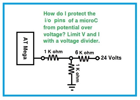
    May I suggest the following:

    image

    • Cancel
    • Vote Up 0 Vote Down
    • Sign in to reply
    • Verify Answer
    • Cancel
  • mcb1
    0 mcb1 over 13 years ago in reply to billabott

    I think the OP wanted to control a 24v item.

    This is a very good referemce for anyone wanting to measure a 24v voltage.


    One thing that you might see on some circuits is a diode at the pin of the micro that has its anode connected to the supply.

    This makes sure the voltage at the pin can never be more tha 0.5v higher than the supply  ...which strangely fits within most IC specs.


    Of course this theory is only any good if the series resitor is in place otherwise the supply could get driven upwards.


    Mark

    • Cancel
    • Vote Up 0 Vote Down
    • Sign in to reply
    • Verify Answer
    • Cancel
  • billabott
    0 billabott over 13 years ago in reply to mcb1

    You are talking over my head with that diode idea.   The senario as I understood it was that how best to safeguard the microC in case the NFET shorted out completely.  So, Mark, are you saying that there are good reasons to also add the diode you mentioned in addition to the voltage divider in my illustration?  Most NFETs need very little V+I  at the gate to turm them on, but, I aslo believe opto-isolators are a great way to go.

    • Cancel
    • Vote Up 0 Vote Down
    • Sign in to reply
    • Verify Answer
    • Cancel
  • e14 Contributor
    0 e14 Contributor over 13 years ago

    Alright, thanks for all the help so far guys! I stopped at radioshack on my way home from work today and picked up two NPN transistors (TO-220) and started experimenting. Ive gotten myself confused. I connected a digital pin from the arduino to the base pin of the transitor, and then ran the emitter pin through an LED to ground. Without and voltage source on the collector pin, the LED lights up. My original plan was to use 5v from the arduino on the collector. Why is my LED lighting up?

    • Cancel
    • Vote Up 0 Vote Down
    • Sign in to reply
    • Verify Answer
    • Cancel
  • billabott
    0 billabott over 13 years ago in reply to e14 Contributor

    Mason, this tutorial should help you to understand: http://www.electronics-tutorials.ws/transistor/tran_1.html and http://www.electronics-tutorials.ws/transistor/tran_2.html


    Your LED is on because both diode junctions, the Base-Emitter and Anode-Cathode, are forward biased which allows electrons to flow.


    The NPN transistor's output signal, to control a LED or a Motor, should be taken off of the Collector pin to avoid the exact event that you discovered.  A motor would allow too much current through the base and potentially burn up the transistor, don't you think?

    Remember this about Transistor Currents: typically IBE <  0.05 * ICE.   And that implies the Gain is about 20; lots of transistors have a Gain >= 50.


    P.S.  TO-220 is the package style of many widely divergent devices and does not say anything about its performance characteristics.

    • Cancel
    • Vote Up 0 Vote Down
    • Sign in to reply
    • Verify Answer
    • Cancel
  • johnbeetem
    0 johnbeetem over 13 years ago

    Here's a short Raspberry Pi discussion about driving a 5V relay from a RasPi GPIO.  The second comment shows a simple NPN transistor circuit.  I believe you can use the same circuit with your 24V external device provided that you select a transistor with a high voltage rating.  [This opinion provided without warranty.]


    Note that the circuit has a 1K current limiting resistor between the GPIO and transistor base.  You don't want to drive an NPN transistor base directly from a GPIO with the transistor's emitter grounded, because the voltage drop across the transistor base-emitter junction should not be more than 0.6 volts and if the GPIO pin tries to pull it up to 3.3V you're likely to damage something.  The 1K resistor limits the current to about 2.7mA assuming a 3.3V GPIO, or about 4.4mA with a 5V GPIO.


    The transistor multiplies current by a factor of "beta", with is typically 10-20.  That is, the transistor can amplify a 2.7mA current through its base-emitter junction to 27 mA or more through its collector-emitter junction depending on what's hooked up.  If this is not enough current, you can use two NPN transistors in the form of a Darlington Pair, which gives you a current multiplication of "beta" squared.


    Before using your external 24V device, be sure to test using an LED so you can tell if you've got things hooked up correctly.  You typically want to limit LED current to 2-5mA, which means you need a 5-10K resistor between the LED and 24V.  The voltage drop across a working LED is 2.4V or so, depending on color.  If you put more than that across an LED, it will emit a very bright light once before it turns into a DED (dark-emitting diode).


    Edit: a high-voltage transistor with at least 40V reverse breakdown voltage should be all the protection you need.  However, since 24V will easily kill a micro-controller, if you're worried you can use a 5V relay or opto-isolator to control the 24V circuit.

    • Cancel
    • Vote Up +1 Vote Down
    • Sign in to reply
    • Verify Answer
    • Reject Answer
    • Cancel
>
element14 Community

element14 is the first online community specifically for engineers. Connect with your peers and get expert answers to your questions.

  • Members
  • Learn
  • Technologies
  • Challenges & Projects
  • Products
  • Store
  • About Us
  • Feedback & Support
  • FAQs
  • Terms of Use
  • Privacy Policy
  • Legal and Copyright Notices
  • Sitemap
  • Cookies

An Avnet Company © 2026 Premier Farnell Limited. All Rights Reserved.

Premier Farnell Ltd, registered in England and Wales (no 00876412), registered office: Farnell House, Forge Lane, Leeds LS12 2NE.

Follow element14

  • X
  • Facebook
  • linkedin
  • YouTube