element14 Community
element14 Community
    Register Log In
  • Site
  • Search
  • Log In Register
  • About Us
  • Community Hub
    Community Hub
    • What's New on element14
    • Feedback and Support
    • Benefits of Membership
    • Personal Blogs
    • Members Area
    • Achievement Levels
  • Learn
    Learn
    • Ask an Expert
    • eBooks
    • element14 presents
    • Learning Center
    • Tech Spotlight
    • STEM Academy
    • Webinars, Training and Events
    • Learning Groups
  • Technologies
    Technologies
    • 3D Printing
    • FPGA
    • Industrial Automation
    • Internet of Things
    • Power & Energy
    • Sensors
    • Technology Groups
  • Challenges & Projects
    Challenges & Projects
    • Design Challenges
    • element14 presents Projects
    • Project14
    • Arduino Projects
    • Raspberry Pi Projects
    • Project Groups
  • Products
    Products
    • Arduino
    • Avnet Boards Community
    • Dev Tools
    • Manufacturers
    • Multicomp Pro
    • Product Groups
    • Raspberry Pi
    • RoadTests & Reviews
  • Store
    Store
    • Visit Your Store
    • Choose another store...
      • Europe
      •  Austria (German)
      •  Belgium (Dutch, French)
      •  Bulgaria (Bulgarian)
      •  Czech Republic (Czech)
      •  Denmark (Danish)
      •  Estonia (Estonian)
      •  Finland (Finnish)
      •  France (French)
      •  Germany (German)
      •  Hungary (Hungarian)
      •  Ireland
      •  Israel
      •  Italy (Italian)
      •  Latvia (Latvian)
      •  
      •  Lithuania (Lithuanian)
      •  Netherlands (Dutch)
      •  Norway (Norwegian)
      •  Poland (Polish)
      •  Portugal (Portuguese)
      •  Romania (Romanian)
      •  Russia (Russian)
      •  Slovakia (Slovak)
      •  Slovenia (Slovenian)
      •  Spain (Spanish)
      •  Sweden (Swedish)
      •  Switzerland(German, French)
      •  Turkey (Turkish)
      •  United Kingdom
      • Asia Pacific
      •  Australia
      •  China
      •  Hong Kong
      •  India
      •  Korea (Korean)
      •  Malaysia
      •  New Zealand
      •  Philippines
      •  Singapore
      •  Taiwan
      •  Thailand (Thai)
      • Americas
      •  Brazil (Portuguese)
      •  Canada
      •  Mexico (Spanish)
      •  United States
      Can't find the country/region you're looking for? Visit our export site or find a local distributor.
  • Translate
  • Profile
  • Settings
Arduino
  • Products
  • More
Arduino
Arduino Forum What are the Arduino IDE pin assignments?
  • Blog
  • Forum
  • Documents
  • Quiz
  • Events
  • Polls
  • Files
  • Members
  • Mentions
  • Sub-Groups
  • Tags
  • More
  • Cancel
  • New
Join Arduino to participate - click to join for free!
Actions
  • Share
  • More
  • Cancel
Forum Thread Details
  • State Suggested Answer
  • Replies 12 replies
  • Answers 8 answers
  • Subscribers 392 subscribers
  • Views 8056 views
  • Users 0 members are here
  • pin
  • ide
  • assignment
  • mapping
Related

What are the Arduino IDE pin assignments?

Former Member
Former Member over 11 years ago

I am going to write a program for an existing ATmega32 processor and was trying to understand the pin number assignments. As an example the blink program has the following code.


// Pin 13 has an LED connected on most Arduino boards.

// give it a name:

int led = 13;


But the key word is "MOST" and it is a pin number which has a mapping to a processor I/O pin. On the UNO the LED is on pin 19/PB5. I wanted to understand why this was 13 and wanted a way to use an more understandable translation from code to hardware. For example:


// LED connected to PB5.

// give it a name:

int led = PB5;


PB5 is defined in one of the iomXX.h files that depend on the processor.

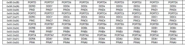
This would work if PB5 was mapped to the processor's pin used for port B bit 5, but it is not. It is assigned the value of 5.

PA5, PB5, PC5 and PD5 are all assigned the value of 5.


I analyzed the pins_arduino.h files to understand the pin mapping so I could define a value for the pins that would map to the processor's pins. For example on a ATmega32 the following definitions give variable names to the pins. This is not the pin on the microprocessor, but the pin number that the Arduino IDE uses to communicate with the functions like digitalWrite(8,HIGH) with set PinB0 high.


static const uint8_t PinB0 = 8;

static const uint8_t PinB1 = 9;

static const uint8_t PinB2 = 10;

static const uint8_t PinB3 = 11;

static const uint8_t PinB4 = 12;

static const uint8_t PinB5 = 13;

static const uint8_t PinB6 = 14;

static const uint8_t PinB7 = 15;


Using these definitions I can write code that I use to wire up my LED.


// LED connected to PinB5.

// give it a name:

int led = PinB5;


So here is my question. I really wanted the variable name to be PB0, not PinB0 since that is the name the datasheet uses, but that name is already defined in iom32.h.

What is the reason that PBx is defined in iom32.h?


Is there some combination of the pin assignments in iom32.h that I should be using that give me the mapping to the pin number, or is there some documentation that defines the mapping?

  • Sign in to reply
  • Cancel

Top Replies

  • shabaz
    shabaz over 7 years ago in reply to sbkenn +2 suggested
    Hi Shane, As I understand (been a while since I tried Arduino, so this information is just general), you can directly ignore nearly all Arduino functions (you'll still need the usual starting function…
  • Former Member
    Former Member over 11 years ago in reply to ntewinkel +1 suggested
    Thanks for the fast response. Again let me ask the question (without all the support statements) with different words. It isn't about the UNO or any board, it is about the microprocessor and the datasheet…
  • ntewinkel
    ntewinkel over 11 years ago in reply to Former Member +1 suggested
    Hi Bill, I don't know, but I wonder if the other definitions are used for direct port manipulation: http://arduino.cc/en/Reference/PortManipulation So it looks like PB5 can only be used when looking at…
Parents
  • ntewinkel
    0 ntewinkel over 11 years ago

    Hi Bill,


    The pins are marked on the board itself. When the sample says pin 13, that's shorthand for D13 = digital 13. When referencing Analogue pins you would use A0, A1, etc.


    Take a look at the picture of the Uno here and you'll see all the I/O ports are marked with numbers:

    http://arduino.cc/en/uploads/Main/ArduinoUno_r2_front.jpg


    More details about the Uno:

    http://arduino.cc/en/Main/arduinoBoardUno


    Hope that helps image


    Cheers,

    -Nico

    • Cancel
    • Vote Up 0 Vote Down
    • Sign in to reply
    • Verify Answer
    • Reject Answer
    • Cancel
  • Former Member
    0 Former Member over 11 years ago in reply to ntewinkel

    Thanks for the fast response. Again let me ask the question (without all the support statements) with different words.


    It isn't about the UNO or any board, it is about the microprocessor and the datasheet. I have a board with a Atmega32 that is not an Arduino board.

    The robot motor pins_arduino.h does create definitions for some of the pins and that is how I have done it also, but I didn't understand why PB5 and PINB5 are already defined because these would have been my first 2 choices for variable names. I was forced to pick a less obvious name pinB5 which is too close to PINB5 and will cause errors that will be very difficult to debug since the compiler will be happy to use PINB5 = 5 instead of pinB5 = 13.


    1. Is there a variable defined that I can use for Arduino calls that relates to the datasheet that I can get from Atmel?

               I think the answer to this is NO.


    2. The variable I would like as an example is PB5, however it is already defined as something else. Why? What is that definition used for?

              I think the answer is "it is not used for anything"


    3. Is there some combination of variables already defined that I should be using? I.E. PB5, DDB5, PINB5 etc. None of these seem to lead to a datasheet.

              Again I think the answer is NO.


    I am hoping someone can either verify my answers or tell me a way to write code that doesn't require a pin map to find the correct pin on the microprocessor.


    I would like to see this:

         pinMode (PB5, OUTPUT);

         digitalWrite(PB5, HIGH):

    Not this:

         pinMode (13, OUTPUT);

         digitalWrite(13, HIGH);

    • Cancel
    • Vote Up +1 Vote Down
    • Sign in to reply
    • Verify Answer
    • Reject Answer
    • Cancel
  • ntewinkel
    0 ntewinkel over 11 years ago in reply to Former Member

    Hi Bill,


    I don't know, but I wonder if the other definitions are used for direct port manipulation: http://arduino.cc/en/Reference/PortManipulation

    So it looks like PB5 can only be used when looking at port B, but that doesn't make sense to me either (like why call it PB5 if it's not specific to port B to begin with? call it pin5 then).


    I see your point about PB5 - to me, from looking at all those pretty and promising pictures, it seems that PB5 references ONLY the one pin, so it makes no sense to give it a value that doesn't specifically apply to that pin on the chip.


    And I too was surprised that the Arduino IDE wouldn't allow 13 to be freely interchangeable with PB5. This picture also shows it defined like that: Arduino - PinMapping168

    And why can't I put D13 instead of 13?


    Maybe this is a restriction in the Arduino IDE (designed to simplify) ? I know there are other IDEs available to program the chip directly, so maybe that's where the other definitions come into play.


    In short, I have no answers, just more questions image


    I hope someone else can clarify this for us!


    Cheers,

    -Nico


    • Cancel
    • Vote Up +1 Vote Down
    • Sign in to reply
    • Verify Answer
    • Reject Answer
    • Cancel
  • ntewinkel
    0 ntewinkel over 11 years ago in reply to Former Member

    Just found this: http://forum.arduino.cc/index.php?topic=37067.0


    Apparently using PORTB5 correctly identifies digital13 (and compiles in my IDE).


    And I still don't know why any of that is supposed to make sense image

    • Cancel
    • Vote Up +1 Vote Down
    • Sign in to reply
    • Verify Answer
    • Reject Answer
    • Cancel
Reply
  • ntewinkel
    0 ntewinkel over 11 years ago in reply to Former Member

    Just found this: http://forum.arduino.cc/index.php?topic=37067.0


    Apparently using PORTB5 correctly identifies digital13 (and compiles in my IDE).


    And I still don't know why any of that is supposed to make sense image

    • Cancel
    • Vote Up +1 Vote Down
    • Sign in to reply
    • Verify Answer
    • Reject Answer
    • Cancel
Children
  • Former Member
    0 Former Member over 11 years ago in reply to ntewinkel

    Compiling and running are two different things. To compile, the syntax needs to be correct, to run the program needs to do the correct thing.

    For example pinMode(13, OUTPUT) compiles and so does pinMode(PB5,OUTPUT), but the first changes digital output D13 and the second changes digital output D5 (because PB5 = 5);


    The example at http://forum.arduino.cc/index.php?topic=37067.0 is a good example of the use of low level commands. The program write directly to the register and changes the bit.

    Based on the comments by the author, they did this to create a I2C type of signal but the signal required is slightly different from I2C. The reason for low level commands would be timing. Using a digitalWrite command would create a lot of extra lines of code that need to be executed and may not be tolerated in communicating with this device.


    First a few definitions used in the program - mostly from included files.

    #define PORTB _SFR_IO8(0x05) from iom328p.h

    #define _SFR_IO8(io_addr) ((io_addr) + __SFR_OFFSET) --- from sfr_defs.h

         This defines the register's address. __SFR_OFFSET is 0x00 or 0x20 depending on the processor

    In the table below from the Atmega328 processor, you can see that the PORTB register is at address 0x05

    .image

    Now from the code example...

    #define SETSCK1 PORTB |= (1<<PB5)          

         1<<PB5 => shift 1 left 5 places => 0010 0000 (space in binary number for ease of reading)

         |= => OR the register PORTB with the bits - sets the 6th bit


    #define SETSCK0 PORTB &= ~(1<<PB5)

         1<<PB5 => shift 1 left 5 places => 0010 0000 (space in binary number for ease of reading)

        ~(1<<PB5)  => invert the bits => 1101 1111

         &= => and the register PORTB with the bits - clearing the 6th bit


    #define SCKOUTP DDRB |= (1<<DDB5)

         DDRB is the Data Direction Register for port B defined as 0x04. DDB5 = 5.  Setting a bit to a 1 sets the pin to OUTPUT


    Sorry if I vented too much, but hope it was a little educational.


    Now back to my gripe..

    PB5 = 5. It doesn't really have anything to do with port B. It is just bit 5 (but the B doesn't stand for BIT because there is a PC5 also).

    OK. Now I see a little support for PB5, PC5 etc but they could have all been BIT5 then my problem wouldn't exist.

    However, this example helps me in that it is only the coder using these definitions and not the libraries.

    • Cancel
    • Vote Up +1 Vote Down
    • Sign in to reply
    • Verify Answer
    • Reject Answer
    • Cancel
element14 Community

element14 is the first online community specifically for engineers. Connect with your peers and get expert answers to your questions.

  • Members
  • Learn
  • Technologies
  • Challenges & Projects
  • Products
  • Store
  • About Us
  • Feedback & Support
  • FAQs
  • Terms of Use
  • Privacy Policy
  • Legal and Copyright Notices
  • Sitemap
  • Cookies

An Avnet Company © 2025 Premier Farnell Limited. All Rights Reserved.

Premier Farnell Ltd, registered in England and Wales (no 00876412), registered office: Farnell House, Forge Lane, Leeds LS12 2NE.

ICP 备案号 10220084.

Follow element14

  • X
  • Facebook
  • linkedin
  • YouTube