element14 Community
element14 Community
    Register Log In
  • Site
  • Search
  • Log In Register
  • Community Hub
    Community Hub
    • What's New on element14
    • Feedback and Support
    • Benefits of Membership
    • Personal Blogs
    • Members Area
    • Achievement Levels
  • Learn
    Learn
    • Ask an Expert
    • eBooks
    • element14 presents
    • Learning Center
    • Tech Spotlight
    • STEM Academy
    • Webinars, Training and Events
    • Learning Groups
  • Technologies
    Technologies
    • 3D Printing
    • FPGA
    • Industrial Automation
    • Internet of Things
    • Power & Energy
    • Sensors
    • Technology Groups
  • Challenges & Projects
    Challenges & Projects
    • Design Challenges
    • element14 presents Projects
    • Project14
    • Arduino Projects
    • Raspberry Pi Projects
    • Project Groups
  • Products
    Products
    • Arduino
    • Avnet & Tria Boards Community
    • Dev Tools
    • Manufacturers
    • Multicomp Pro
    • Product Groups
    • Raspberry Pi
    • RoadTests & Reviews
  • About Us
    About the element14 Community
  • Store
    Store
    • Visit Your Store
    • Choose another store...
      • Europe
      •  Austria (German)
      •  Belgium (Dutch, French)
      •  Bulgaria (Bulgarian)
      •  Czech Republic (Czech)
      •  Denmark (Danish)
      •  Estonia (Estonian)
      •  Finland (Finnish)
      •  France (French)
      •  Germany (German)
      •  Hungary (Hungarian)
      •  Ireland
      •  Israel
      •  Italy (Italian)
      •  Latvia (Latvian)
      •  
      •  Lithuania (Lithuanian)
      •  Netherlands (Dutch)
      •  Norway (Norwegian)
      •  Poland (Polish)
      •  Portugal (Portuguese)
      •  Romania (Romanian)
      •  Russia (Russian)
      •  Slovakia (Slovak)
      •  Slovenia (Slovenian)
      •  Spain (Spanish)
      •  Sweden (Swedish)
      •  Switzerland(German, French)
      •  Turkey (Turkish)
      •  United Kingdom
      • Asia Pacific
      •  Australia
      •  China
      •  Hong Kong
      •  India
      •  Japan
      •  Korea (Korean)
      •  Malaysia
      •  New Zealand
      •  Philippines
      •  Singapore
      •  Taiwan
      •  Thailand (Thai)
      •  Vietnam
      • Americas
      •  Brazil (Portuguese)
      •  Canada
      •  Mexico (Spanish)
      •  United States
      Can't find the country/region you're looking for? Visit our export site or find a local distributor.
  • Translate
  • Profile
  • Settings
Arduino
  • Products
  • More
Arduino
Arduino Forum Help, my Processing code is restarting my Arduino code
  • Blog
  • Forum
  • Documents
  • Quiz
  • Events
  • Polls
  • Files
  • Members
  • Mentions
  • Sub-Groups
  • Tags
  • More
  • Cancel
  • New
Join Arduino to participate - click to join for free!
Actions
  • Share
  • More
  • Cancel
Forum Thread Details
  • State Verified Answer
  • Replies 35 replies
  • Answers 1 answer
  • Subscribers 421 subscribers
  • Views 4050 views
  • Users 0 members are here
Related

Help, my Processing code is restarting my Arduino code

kjhart0133
kjhart0133 over 12 years ago

Hello all,

I'm developing some Arduino code using XBees to sense environmental data at a remote location. My Arduino code is working great and I'm now ready to upload my remotely acquired data to my computer so that I can parse the data and send it via an SMS message to my smart phone. This way I can monitor my remote location from anywhere.

I'm using a chunk of code I got from the "Getting Started with Processing" book by Reas and Fry. I am able to get the Arduino/XBee data into my computer this way, but I have a problem/issue:

The Arduino code loops continually, but each time I start the Processing Code, it restarts (resets?) the Arduino code. The Arduino code starts over from the beginning going through setup and then into the loop. I have no idea why this is happening. Here is the Processing code I'm using:

// Based on Example 11-07 from "Getting Started with Processing"

// by Reas & Fry. O'Reilly / Make 2010

// This sketch, as modified by kjh, reads data from an Arduino, stores it in an array

// then saves the data to a file on disk.


import processing.serial.*;


Serial port;                     // Create object from Serial class

int asize = 8;                 // define size of data array

byte[] val = new byte[asize];    // Data received from the serial port

                                 // representing the setting of the pot

int i = 0;                       // array index

int x;                           // scratch value

float y;


void setup() {

  //size(440, 220);

  // IMPORTANT NOTE:

  // The first serial port retrieved by Serial.list()

  // should be your Arduino. If not, uncomment the next

  // line by deleting the // before it. Run the sketch

  // again to see a list of serial ports. Then, change

  // the 0 in between [ and ] to the number of the port

  // that your Arduino is connected to.

  println(Serial.list());

  String arduinoPort = Serial.list()[2];

  port = new Serial(this, arduinoPort, 9600);

}


void draw() {

    if (port.available() > 0) {        // If data is available,

      x = port.read();        // read it and store it in val

      val[i] = byte(x);

      y =  float(x);

      //println(y);

      println(val[i]);

      //val = map(val, 0, 255, 0, height);  // Convert the value

      i++;

    }

    if (i > asize-1){

      saveBytes("arduino_data.dat", val);

      println("Data written.");

      exit();

    }

}

My Arduino code does not read data from the computer or Processing, it only sends data to Processing. The Arduino code is quite long and involved using a fair amount of XBee interface code so I didn't include it here. But, as I said, it is running fine except for being restarted each time I run the Processing code.  I'm using an Mega Arduino board connected to my PC via the USB cable. 

I greatly appreciate any assistance on this.

Thanks,

Kevin H.

  • Sign in to reply
  • Cancel

Top Replies

  • kjhart0133
    kjhart0133 over 12 years ago in reply to mcb1 +1
    Success!! After trying a number of different things without solving the problem, I finally cut the jumper on the reset line between the USART and the Mega chip and this did the trick. These forums are…
  • kjhart0133
    kjhart0133 over 12 years ago in reply to kjhart0133 +1
    To solve the problem of now not being able to upload sketches, I soldered a wire to each of the reset line solder pads and wired an SPST switch across the two solder pads. This works perfectly (so far…
  • kjhart0133
    kjhart0133 over 12 years ago in reply to Robert Peter Oakes +1
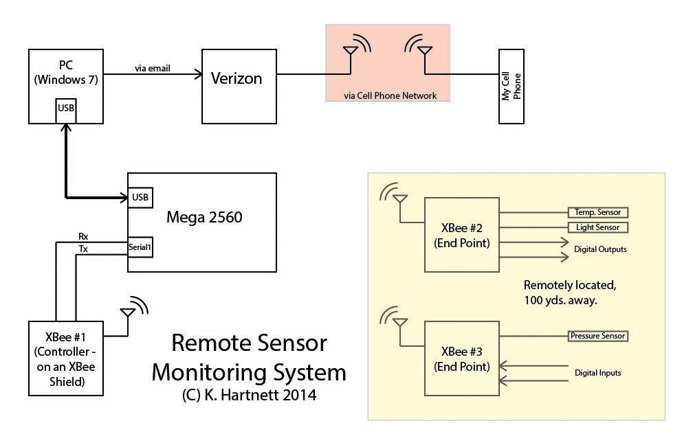
    Peter, That's great info about the ports. I'm learning a lot in this thread. Here's a block diagram of my system that shows all the components. I run Processing code in the PC that uploads data from the…
Parents
  • Robert Peter Oakes
    0 Robert Peter Oakes over 12 years ago

    you are using different USB to serial chips, thats why the difference


    the configuration of drivers is not int he domain of windows itself but in the driver downloaded to control the hardware, one is using the ATMEGA 32U?? built into he board, the other is using the FTDI adapter chip presumably built into a cable or as a separate little board. this is why your not seeing the same settings.


    is the board re-booting really that much of an issue. By leveraging the built in flash of the arduino you can prevent the restarts from loosing your collected data, adding an SD card could also be used. I agree when uploading new code etc to the target would still need addressing if your making use of the same serial connections but that was not indicated int he original question, and unless the monitoring PC is going to be permanently connected to the Bluetooth module there will always be a connection issue of some kind. better to write code to avoid the problem entirly


    can you provide a simple diagram in the post showing how everything is connected together from the PC right through to the remote collection node


    Thanks

    • Cancel
    • Vote Up 0 Vote Down
    • Sign in to reply
    • Verify Answer
    • Cancel
Reply
  • Robert Peter Oakes
    0 Robert Peter Oakes over 12 years ago

    you are using different USB to serial chips, thats why the difference


    the configuration of drivers is not int he domain of windows itself but in the driver downloaded to control the hardware, one is using the ATMEGA 32U?? built into he board, the other is using the FTDI adapter chip presumably built into a cable or as a separate little board. this is why your not seeing the same settings.


    is the board re-booting really that much of an issue. By leveraging the built in flash of the arduino you can prevent the restarts from loosing your collected data, adding an SD card could also be used. I agree when uploading new code etc to the target would still need addressing if your making use of the same serial connections but that was not indicated int he original question, and unless the monitoring PC is going to be permanently connected to the Bluetooth module there will always be a connection issue of some kind. better to write code to avoid the problem entirly


    can you provide a simple diagram in the post showing how everything is connected together from the PC right through to the remote collection node


    Thanks

    • Cancel
    • Vote Up 0 Vote Down
    • Sign in to reply
    • Verify Answer
    • Cancel
Children
  • kjhart0133
    0 kjhart0133 over 12 years ago in reply to Robert Peter Oakes

    Peter,


    That's great info about the ports.  I'm learning a lot in this thread.


    Here's a block diagram of my system that shows all the components.  I run Processing code in the PC that uploads data from the Mega.  The Mega also executes Arduino code that operates the controller XBee, which reads/writes the two end point XBees.


    After fixing the problem with Processing resetting the Mega, I now only have to write some code to parse the data into an email to Verizon; Verizon then sends an SMS to my cell phone.


    Let me know if there are any questions on this.


    Kevin

    image

    • Cancel
    • Vote Up +1 Vote Down
    • Sign in to reply
    • Verify Answer
    • Cancel
  • Robert Peter Oakes
    0 Robert Peter Oakes over 12 years ago in reply to kjhart0133

    Excellent diagram, thanks, very helpful


    So based on your description, when you plug the 2560 into the PC and start your processing application it will cause the Mega to restart, this as already pointed out is due the the USB to Serial chip on the mega issuing a reset to the mega in anticipation of uploading code , it is pretty standard serial communication protocol behavior (Not the reset bit, just the setting of the additional handshaking lines), the up-loader code on the IDE uses this feature to switch the Arduino into the boot-loader and ready it for code upload.


    My first question is :- Is the resetting of the 2560 also causing a reset of the remote Xbee devices due to re-establishing the links ?, if so then connecting the reset line of the XBee #1 to an output pin rather than the same reset as the Arduino would allow this to stop, you would add code to reset the Xbee if needed via the port or simply tie it to the correct logic level. You could add code to the mega to respond to a command to issue a reset instead.


    If it is not causing the remote controllers to reset and it is simply the local Mega 2560 then are you data logging on it or storing certain code into ram until the PC is connected, you could try saving it into the flash ram if that is an option. What I am asking here is why is the resetting an issue ?, what is it doing that is causing a problem for you.


    Perhaps posting your code as a PDF or zip file will be possible, I will be happy to have a look and provide suggestions

    • Cancel
    • Vote Up 0 Vote Down
    • Sign in to reply
    • Verify Answer
    • Cancel
  • Robert Peter Oakes
    0 Robert Peter Oakes over 12 years ago in reply to Robert Peter Oakes

    To add to my previous post, with the 2560, you could also have the XBee connected to serial 2 or 3 rather than the one connected to the same USB interface, you would have to code the serial yourself but that should not be too difficult. the XBee pictures I have been looking at have jumpers rather than the switch to select how the XBee is connecting to the Arduino, simply remove them both and hook into the second serial port instead and adjust your code appropriately... just a thought

    • Cancel
    • Vote Up 0 Vote Down
    • Sign in to reply
    • Verify Answer
    • Cancel
  • ipv1
    0 ipv1 over 12 years ago in reply to kjhart0133

    Things just became a whole lot clearer. I thought you were programming the arduino over the Xbee. I think at this point you are sharing a serial port between the PC/USB/Atmega8u and the xbee. Of course I am possibly wrong.

    There is a better way to do what you are doing... cut out the middle man. If you are going to use the PC with the processing app anyways, get an XBee ftdi adaptor for the Xbee module. Use the processing app to directly access the Xbee and talk to the nodes. This way you cut out the MEGA2560 entirely. This is good if you are not looking to use any other feature of the mega.

    If this makes sense, then we can move onto how to do the above. If not, you might need to give us a better idea of what you are trying to accomplish and more importantly what are your future plans.

    Sincerely,

    IP

    • Cancel
    • Vote Up 0 Vote Down
    • Sign in to reply
    • Verify Answer
    • Cancel
  • mcb1
    0 mcb1 over 12 years ago in reply to ipv1

    Kevin


    You do realise you can get GSM shields and modems that allow you to remove the PC bit.


    Mark

    • Cancel
    • Vote Up 0 Vote Down
    • Sign in to reply
    • Verify Answer
    • Cancel
element14 Community

element14 is the first online community specifically for engineers. Connect with your peers and get expert answers to your questions.

  • Members
  • Learn
  • Technologies
  • Challenges & Projects
  • Products
  • Store
  • About Us
  • Feedback & Support
  • FAQs
  • Terms of Use
  • Privacy Policy
  • Legal and Copyright Notices
  • Sitemap
  • Cookies

An Avnet Company © 2026 Premier Farnell Limited. All Rights Reserved.

Premier Farnell Ltd, registered in England and Wales (no 00876412), registered office: Farnell House, Forge Lane, Leeds LS12 2NE.

Follow element14

  • X
  • Facebook
  • linkedin
  • YouTube