


hi all,
i have used arduino uno to make datalogger for industy.i used sd card,rtc,lcd and some basic ic in my circuit.plz do rply.is it reliable to use arduino in industry?
hi all,
i have used arduino uno to make datalogger for industy.i used sd card,rtc,lcd and some basic ic in my circuit.plz do rply.is it reliable to use arduino in industry?


Hello everyone, my name is Daren. I am an Engineer and Arduino software developer.
This is the question I started asking when I had clients that needed specialized automation systems for industrial applications. I liked the Arduino IDE and had my eyes set on the Due but had no idea what I was getting myself in to. Before I begin to share my experiences and attempt to answer the question of Arduino’s suitability within a large industrial control environment, I should first preface my answer with some insight about the hardware.
Firstly, the Arduino Due is the only board that even comes close to being useful for industrial applications; at least for the main control board. The Uno and Mega are fine for collecting sensor data from remote areas and sending the readings/thresholds to a more capable board via Ethernet for the main logical processing. The primary reason is that the Due is Arm Core 32-bit and doesn’t have the global variable restriction like the Mega for example. The Mega can only have around 200 or so declared variables before it won’t compile which is ridiculously tiny; compared to the Due which can have thousands of variables, only restriction being the flash memory itself. The Due doesn’t have a global variable memory allocation limit like the Mega. That introduces a HUGE increase in software capability that blows the Mega away; the Mega is also very laggy with big sketches even if well written. The Due can handle more than 15,000 lines of code without even breaking a sweat and tops out at somewhere around 26,000 lines and handles an AMAZING 54 interrupts compared to a measly 6 on the Mega which is perfect for complex systems. If your automation system has 26,000 lines of code I hope its mopping the floor too. There are also more powerful Arduino IDE compatible microcontrollers made by Texas Interments and Intel but I don’t have any experience with those and the Due so far has been more than powerful enough.
Another thing worth mentioning is that the Due has no user programmable EEPROM, which makes it seemingly useless for industrial applications, right? Wrong, use the SD card to save all variable states in a prudent interval or under certain conditions and then load all the variables back from the SD upon boot-up. A guy named Alex Shu (http://overskill.alexshu.com/saving-loading-settings-on-sd-card-with-arduino/) made a wonderful example how to very easily and effectively store and recall variables from/to the SD card and its way more simple and effective than using an EEPROM and can have 4GB+ of data.
And lastly, in a big factory often sensor inputs or control outputs will not be close enough to the microcontroller to be effective and usually even a Due will not have enough GPIOs to accommodate a complex environment. So we have resolved this by using Ethernet shields to transmit encoded data to and from all the Due’s, Mega’s and Uno’s throughout the environment. So you can use as many microcontrollers as you need to accommodate your specific needs. We use Telnet servers and clients on the various boards to send the encoded signals between the remote Arduinos and main Arduino(s). Would you believe that Arduino can run multiple telnet server at the same time? It CAN, we used a Telnet server (port 23) on the main board to interface with it, look at logs, start stop machines, etc. and use other ports like 22 on a second Telnet server running on the SAME board to be used only for sending / receiving encoded signals between the networked microcontrollers. This is amazing, you can have many Arduino’s even thousands of feet away (over fiber optic or wireless bridge) from each other sending and receiving signals and threshold data in <10ms intervals before things start to breakdown due to buffer overflow. 10ms intervals is more than low enough for nearly all applications. We have ran at least 4 Telnet servers on a single Due with no problem. I can Telnet into the Due, send commands to the Due that will then trigger a relay on another Arduino over yet another Telnet connection. We have done all of this in large factories with more than 100 IOs spread across 5+ Arduinos, no problem. The important thing to note is that Ethernet or TCP/IP is not going to be susceptible to noise and interference on long sensor runs in the same manner that a GPIO circuit would be. If anyone wants to know how to use Telnet in this manner, let me know. I'm happy to help.
Moving on, the most predominant issue with using Arduino for industrial applications will be interference and likewise inaccurate readings or erroneous pin input signals. You may find in a complex environment that if powering the microcontroller with your laptop everything is fine, then when you power it with an external power supply everything is not fine, and or when your relays trigger something with high current your readings will suddenly become erratic. This leads me to my main point which is that Arduino by itself is neither appropriate nor inappropriate for industrial applications; it is simply a microcontroller, a CPU stamped on to a piece of PCB with conductors leading to and from it. Its incoherent to assert that Arduino by itself inherently is or is not appropriate for industrial applications. That being said, in my professional opinion some Arduinos are of excellent quality and reliability, excellent thermal characteristics an tolerance (40c is not even close to being an issue) and its totally up to all the supporting terminals, components and electronics that determine its industrial worthiness; and of course the manner in which the software is written. But the platform itself I don’t believe is inherently unsuitable for the purpose industrial applications; it’s just a CPU that runs embeded C with IO pins. Sure there are more professional solutions but the price of doing it with Arduino is attractive, the reliability can be obtained, the Arduino IDE has its advantages, the available sensors to choose from is immense and the supporting community is awesome. It is the amalgam of rapid prototyping and production readiness.
Additionally there are purpose built Arduino IDE compatible industrial PLC boards that are what they say, end of discussion.
http://www.e-gizmo.com/KIT/PLC64.html
https://industruino.com/page/home
But, to pursue implementation of a general purpose board a multi-channel Opto isolator board is highly recommended for IOs on the microcontrollers that have sensor input to your environment.
Like this:
or this:
http://www.ebay.com/itm/311520477631
In my experience I have never gotten Arduino to work properly when not powered by a USB cable from a computer unless I isolated the input power from the utility power. Every time I used a regular 220v to 12v switching power supply or wall type transformer sensors were always flaky or didnt work at all. If your sensor reading are erratic, there is interference coming from your power source.
Don’t underestimate this, power and noise caused %99 of all problems we encountered during our research and development. Not only that but some sensors will fail to operate correctly with even the slightest drop in voltage which will occur if you only use power provided by the Arduino itself and have more than only couple things plugged in. The Arduino power regulator put out only something like 140ma and the Due’s CPU itself consumes most of it.
Another thing that is absolutely critical for using Arduino in industrial applications is software signal filtering and debouncing. Look at the example below:
NEVER use the “delay” command except for ultrasound (which uses delayMicros). Always use millis()
if (digitalRead(button6) == LOW) {
if (button6ReadingPrep == true) {
button6LastDebounceTime = millis();
button6ReadingPrep = false;
}
if (millis() - button6LastDebounceTime > buttonDebounceDelay) {
button6State = true;
}
} else {
button6ReadingPrep = true;
}
Then if this is a toggle scenario you can further filter out bogus readings by an additional %50 by disabling that input until the opposing input has been toggled. Like this:
If (button6Toggle == true) {
if (digitalRead(button6) == LOW) {
if (button6ReadingPrep == true) {
button6LastDebounceTime = millis();
button6ReadingPrep = false;
}
if (millis() - button6LastDebounceTime > buttonDebounceDelay) {
button6State = true;
button6Toggle = false;
}
} else {
button6ReadingPrep = true;
}
}
Then if the next stage reaches it condition the “button6Toggle” becomes "true". This is also a way to reduce CPU usage and bogging by terminating unneeded comparisons. Use subroutines often and use the "return" command whenever a process finishes before the end of the loop. contrary to what some developers suggest, the return command is unquestionably beneficial for use in Embedded C on CPU limited hardware. Contrary to what some people claim, Arduino is neither C nor C++; it is embedded C which is its own thing. Traditional rules of C dont always apply nor are always prudent. Microcontroller programming is it's own world and thats why it has it's own language.
Another note, would be to make sensors achieve a quorum of consistency with its readings given a margin before action is taken. Like this:
tankSystemPermeateUltraSoundDuration = pulseIn(tankSystemConfigPermeateEchoPin, HIGH);
tankSystemPermeateUltraSoundDistance = tankSystemPermeateUltraSoundDuration / tankSystemConfigPermeateEchoValue;
if (tankSystemPermeateUltraSoundDistanceCount == 0) {
tankSystemPermeateUltraSoundDistanceFilter = tankSystemPermeateUltraSoundDistance;
}
if (tankSystemPermeateUltraSoundDistance == tankSystemPermeateUltraSoundDistanceFilter || tankSystemPermeateUltraSoundDistance + 1 == tankSystemPermeateUltraSoundDistanceFilter || tankSystemPermeateUltraSoundDistance - 1 == tankSystemPermeateUltraSoundDistanceFilter) {
tankSystemPermeateUltraSoundDistanceCount += 1;
} else {
tankSystemPermeateUltraSoundDistanceCount = 0;
}
if (tankSystemPermeateUltraSoundDistanceCount == 3) {
tankSystemPermeateUltraSoundDistanceFinal = tankSystemPermeateUltraSoundDistanceFilter;
tankSystemPermeateUltraSoundDistanceCount = 0;
}
tankSystemPermeateUltraSoundReadingStep2 = true;
tankSystemPermeateUltraSoundReadingStep3 = false;
}
Basically here, the “tankSystemPermeateUltraSoundDistanceFinal” is result of 3 consistent readings that were within at least 1cm of each other.
Another word of advice from experience, use waterproof enclosures to seal your microcontrollers and connect your microcontroller box to another input output wiring enclosure. I live in the Philippines and its always hot, wet and damp, very dirty power and fluctuation; everything gets pushed to the extreme here.
I recommend using 66M1-50 (66-Block) punch down blocks for input and output connection and connect the two enclosures together using RJ-21 cable/connectors. That will allow you to quickly detach the microcontroller box from the wiring box for service.
http://www.ebay.com/itm/25-pair-Telco-Cable-Cat-3-PBX-KSU-RJ21-AMP-connectors-M-F-6Ft-/121812808381
These are the best enclosures. Made by Gewiss, they can be partially unscrewed and then swung open, very convenient. You can easily drill holes for buttons and displays.
Use bullet terminals to easily detach enclosure from power sources.
If your looking for the Pro way to do this, DON’T use a breadboard, that always has the potential to be flakey. Buy your own female/male Dupont terminals and a crimp tool so you can make your own connections from Arduino pins using your own 22 gauge wire with dupont terminal and then punch the the other end into a 66 block, then screw all the ground leads to a common ground screw terminal using fork/spade terminals. This insures that all input ground leads are solidly connected to ground, that all inputs/outputs easily are reroutable via the 66 block and that you have 22 gauge wire all the way from Arduino to the sensor, switch, whatever. Those dupont wires are such crap, 28gauge wire and the pins are flaky. If you follow this suggestion you can have 100+ IOs and not get bogus readings and if you have expensive pumps, motors or critical safety sensors you'll have wiring you can depend on. Always write your software so safety/critical switches are configured in a NORMALLY CLOSED configuration, that way if you have a wiring failure you can check the sensor before the system even starts.
In closing, we have automated factories that have more than 100 IOs with sensors more than 40m away. Arduino is reliable and serves us well. Embedded C language is very well suited for automation and we have been very pleased with the results. Our sketches are in excess of 14,000 lines of code. As a core I recommend Due or grater, be careful how you write your code, make as few concurrent comparisons as needed and if you need to have many concurrent elapsed time counters, use a common global timer and use comparators to compare start times and ending/current times. I have written a very simple global timer/comparator, I know time calculations can be tricky so just ask if you need it.
I'm sure I’m forgetting some things but I hope this helps. If anyone has any questions or needs help feel frees to ask. If you have a specific environment you need help creating I can give you general guidance. I know how to make Arduino rock soiled for industrial applications and I'm willing to share that with anybody in need. And of course, if anyone has learned cool things please feel free to share aswell. If anyone knows about RS-485 interfacing for example, id love to learn more about that…

Hello Daren,
thanks for some useful information. Great to see Due being used in such installations. I am planning on using it for my home automation and I got a few questions if you don't mind answering them.
1. A switch on a long wire. So let's say you have Due on one side of the room and a switch quite a few meters away. You mention that you usually just use a shielded 24+awg wire. Is that directly connected to Due pin with internal pullup on? I am guessing that normally the line is pulled down to GND (normally closed circuit) and when switch is pressed, circuit opens and the line is pulled up to 3.3V. Is that how you connect it? A long wire can cause significant voltage drop so could not it happen that if the circuit is closed the voltage on input will not drop below the threshold (2V) due to voltage drop on that long wire and the pin will stay high? Also are you not afraid that a voltage spike (I guess it can happen even though the cable is shielded) will damage Due's input pin?I guess I would at least go with something like this at a minimum if connecting directly. But considering optocouplers are much more safe I'll probably go with them for inputs and outputs.
2. I must say I got a bit lost when reading about different options for powering Due and sensors. So I'll ask this way. What's the best way of powering Due and external sensors from the noise perspective? Is it better to be powered from the same source or from different ones? I am planning on using Mean Well 230V/5V (like PS-05-5 (5W) or PS-15-5 (15W)) to power Due via usb connector. So Due will be powered via on-board 3.3V regulator. Now, some sensors are 3.3V, some are 5V. Considering Due's regulator would probably not be able to power all 3.3V sensors, I guess I need a dedicated regulator for them (a linear one, like AMS1117 3.3V). That should hopefully also help with noise that Due and sensors put back onto their power lines. 5V sensors would be powered directly from the Mean Well supply and I am not really sure about that. Mean Well supply is a switching one (albeit it should be a quality one). I fear that the switched output will cause erratic readings from the 5V sensors. Would I be better off starting with let's say a 7V power supply, feeding that to DC power input of Due (which has it's own 5V switching and 3.3V linear regulator) and also to a 5V linear regulator for powering 5V sensors. Output of that 5V linear regulator would also be used for powering a 3.3V linear regulator for 3.3V sensors. Thoughts? 
Btw. "Alternatively you can power the Arduino Due directly by feeding the breadboard power regulator output directly to the unregulated 3.3v and 5v pins on the Due.". According to documentation, "Supplying voltage via the 5V or 3.3V pins bypasses the regulator, and can damage your board. We don't advise it.". Just sayin'.
3. From reading I get you connect Due via Dupont connectors. Do you find it reliable? I mean they must be wobbly at least a bit. The best thing would be to solder the wires directly to Due's pins but it's fiddly and makes Due not really replaceable. So I think the second best thing is to make a shield that uses pin headers. Pins on those are a bit thicker than dupont pins (so hopefully a better connection) and the shield won't wobble (it's also used as a way to connect arduino in products like this).
Marek
Hello Daren,
thanks for some useful information. Great to see Due being used in such installations. I am planning on using it for my home automation and I got a few questions if you don't mind answering them.
1. A switch on a long wire. So let's say you have Due on one side of the room and a switch quite a few meters away. You mention that you usually just use a shielded 24+awg wire. Is that directly connected to Due pin with internal pullup on? I am guessing that normally the line is pulled down to GND (normally closed circuit) and when switch is pressed, circuit opens and the line is pulled up to 3.3V. Is that how you connect it? A long wire can cause significant voltage drop so could not it happen that if the circuit is closed the voltage on input will not drop below the threshold (2V) due to voltage drop on that long wire and the pin will stay high? Also are you not afraid that a voltage spike (I guess it can happen even though the cable is shielded) will damage Due's input pin?I guess I would at least go with something like this at a minimum if connecting directly. But considering optocouplers are much more safe I'll probably go with them for inputs and outputs.
2. I must say I got a bit lost when reading about different options for powering Due and sensors. So I'll ask this way. What's the best way of powering Due and external sensors from the noise perspective? Is it better to be powered from the same source or from different ones? I am planning on using Mean Well 230V/5V (like PS-05-5 (5W) or PS-15-5 (15W)) to power Due via usb connector. So Due will be powered via on-board 3.3V regulator. Now, some sensors are 3.3V, some are 5V. Considering Due's regulator would probably not be able to power all 3.3V sensors, I guess I need a dedicated regulator for them (a linear one, like AMS1117 3.3V). That should hopefully also help with noise that Due and sensors put back onto their power lines. 5V sensors would be powered directly from the Mean Well supply and I am not really sure about that. Mean Well supply is a switching one (albeit it should be a quality one). I fear that the switched output will cause erratic readings from the 5V sensors. Would I be better off starting with let's say a 7V power supply, feeding that to DC power input of Due (which has it's own 5V switching and 3.3V linear regulator) and also to a 5V linear regulator for powering 5V sensors. Output of that 5V linear regulator would also be used for powering a 3.3V linear regulator for 3.3V sensors. Thoughts?
Btw. "Alternatively you can power the Arduino Due directly by feeding the breadboard power regulator output directly to the unregulated 3.3v and 5v pins on the Due.". According to documentation, "Supplying voltage via the 5V or 3.3V pins bypasses the regulator, and can damage your board. We don't advise it.". Just sayin'.
3. From reading I get you connect Due via Dupont connectors. Do you find it reliable? I mean they must be wobbly at least a bit. The best thing would be to solder the wires directly to Due's pins but it's fiddly and makes Due not really replaceable. So I think the second best thing is to make a shield that uses pin headers. Pins on those are a bit thicker than dupont pins (so hopefully a better connection) and the shield won't wobble (it's also used as a way to connect arduino in products like this).
Marek
The solution in your link would not be reliable.
Typical micro-controller pins require to be pulled down to less than 20% of the supply to register a low input or above 80% to register a high.
To achieve this:
Change the pull up resistor to 10k and keep the input resistor at 1k.
The 10uF cap across the switch is too large and may shorten the life of the switch (this will depend on the switch of course - if using small pcb button type switches replace it with a 1uF 50V (or greater) ceramic capacitor which can be wired either way round.
The 20M input resistor is far too big(so the micro pin will be susceptible to interference and leakage currents) - the diodes will limit the input voltage even under fault conditions to less than 2V above or below the supply rails - you need to limit the current into the micro's input protection diodes to less than 1mA so that 20M could be 2k and you would be no less protected. I would use 10k which means that the micro input 'sees' source resistance of 20k (switch open) and 10.9k (switch closed).
The ferrite ring is often helpful - put both wires though the same one.
Although opto-couplers can be helpful the LED in them can still be damaged by transients and might even be energized by RF picked up in long wires. They are much tougher than a typical micro-controller input. The disadvantage is that they need power on the input side and unless you use isolated supplies for this you lose quite alot of the advantage. For home automation I don't think you need optos.
MK
Thanks for your comments Michael. The switch will be a normal wall switch that you use to switch 230V lights in regular home installations (home automation has to be reversible) so I won't be using a capacitor on the switch end. 20M resistor is inside the microcontroller so you can't do much about it  I guess it's just for illustration. I still feel I need to protect Arduino Due as my main controller a bit more, it's always easier to replace an opto than the whole board. I plan on using isolated power supplies, 12V (or 24V) on the switch side, 5V/3.3V on the controller side. I think 3.3V is too low voltage to be used on long wires as a pull-up voltage. Anyhow, I came up with this circuit, feel free to comment on it. I will probably include a ferrite ring as well.
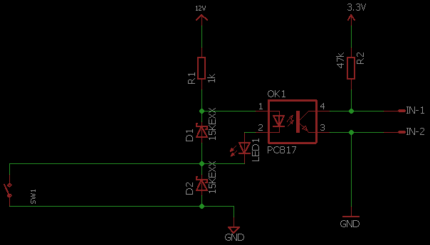
I would use 4k7 rather than 47k for R2, and make sure the opto-coupler transfer ratio is greater than 20%.
If D1 and D2 are transient absorber type devices they will be much more effective than normal zener diodes.
I doubt that the micro really has a 20M resistor inside but as an input the leakage current is quite low.
MK
Thanks for your input Michael. D1, D2 were meant to be some Schottky diodes but I can specifically look for transient absorber ones.
