element14 Community
element14 Community
    Register Log In
  • Site
  • Search
  • Log In Register
  • About Us
  • Community Hub
    Community Hub
    • What's New on element14
    • Feedback and Support
    • Benefits of Membership
    • Personal Blogs
    • Members Area
    • Achievement Levels
  • Learn
    Learn
    • Ask an Expert
    • eBooks
    • element14 presents
    • Learning Center
    • Tech Spotlight
    • STEM Academy
    • Webinars, Training and Events
    • Learning Groups
  • Technologies
    Technologies
    • 3D Printing
    • FPGA
    • Industrial Automation
    • Internet of Things
    • Power & Energy
    • Sensors
    • Technology Groups
  • Challenges & Projects
    Challenges & Projects
    • Design Challenges
    • element14 presents Projects
    • Project14
    • Arduino Projects
    • Raspberry Pi Projects
    • Project Groups
  • Products
    Products
    • Arduino
    • Avnet Boards Community
    • Dev Tools
    • Manufacturers
    • Multicomp Pro
    • Product Groups
    • Raspberry Pi
    • RoadTests & Reviews
  • Store
    Store
    • Visit Your Store
    • Choose another store...
      • Europe
      •  Austria (German)
      •  Belgium (Dutch, French)
      •  Bulgaria (Bulgarian)
      •  Czech Republic (Czech)
      •  Denmark (Danish)
      •  Estonia (Estonian)
      •  Finland (Finnish)
      •  France (French)
      •  Germany (German)
      •  Hungary (Hungarian)
      •  Ireland
      •  Israel
      •  Italy (Italian)
      •  Latvia (Latvian)
      •  
      •  Lithuania (Lithuanian)
      •  Netherlands (Dutch)
      •  Norway (Norwegian)
      •  Poland (Polish)
      •  Portugal (Portuguese)
      •  Romania (Romanian)
      •  Russia (Russian)
      •  Slovakia (Slovak)
      •  Slovenia (Slovenian)
      •  Spain (Spanish)
      •  Sweden (Swedish)
      •  Switzerland(German, French)
      •  Turkey (Turkish)
      •  United Kingdom
      • Asia Pacific
      •  Australia
      •  China
      •  Hong Kong
      •  India
      •  Korea (Korean)
      •  Malaysia
      •  New Zealand
      •  Philippines
      •  Singapore
      •  Taiwan
      •  Thailand (Thai)
      • Americas
      •  Brazil (Portuguese)
      •  Canada
      •  Mexico (Spanish)
      •  United States
      Can't find the country/region you're looking for? Visit our export site or find a local distributor.
  • Translate
  • Profile
  • Settings
Arduino
  • Products
  • More
Arduino
Arduino Forum LED Button push light up
  • Blog
  • Forum
  • Documents
  • Quiz
  • Events
  • Polls
  • Files
  • Members
  • Mentions
  • Sub-Groups
  • Tags
  • More
  • Cancel
  • New
Join Arduino to participate - click to join for free!
Actions
  • Share
  • More
  • Cancel
Forum Thread Details
  • State Not Answered
  • Replies 38 replies
  • Subscribers 389 subscribers
  • Views 25978 views
  • Users 0 members are here
  • sequence
  • led
  • button
Related

LED Button push light up

Josephmbrandtii
Josephmbrandtii over 3 years ago

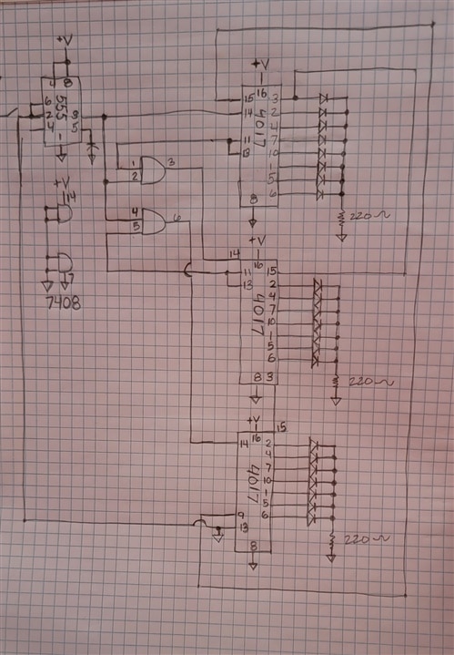
Attempting to make a Cornhole score board with 21 lights that light up at each button push.  At the end of the chain i want it to shut off the lights so there is none.  I am very new to this and have only gotten to the research part.  Any help i can get will be amazing.  Thank you.

  • Sign in to reply
  • Cancel

Top Replies

  • beacon_dave
    beacon_dave over 3 years ago +7
    Is the button to be controlled by a person or is the button controlled automatically by the cornsack/beanbag passing through the hole in the board ? What sort of lights are you planning on using ? Individual…
  • javagoza
    javagoza over 3 years ago +5
    Maybe you can use addressable LEDs https://www.makerguides.com/how-to-control-ws2812b-individually-addressable-leds-using-arduino/
  • geralds
    geralds over 3 years ago in reply to Josephmbrandtii +5
    Hi, here a suggestion: As I saw you have drawn it from the example from the datasheet. Now this is the complete circuit including the bypass capacitors and one of a possible method to make the…
Parents
  • dougw
    0 dougw over 3 years ago

    It sounds like you could just connect a 22 bit Johnson counter to 21 lights with a debounced button to count up. Three CD4017 chips (~$0.11 each) cascaded would could make a 21 bit Johnson counter. You would need a MOSFET on each output to drive each light.

    • Cancel
    • Vote Up +3 Vote Down
    • Sign in to reply
    • Verify Answer
    • Cancel
  • Josephmbrandtii
    0 Josephmbrandtii over 3 years ago in reply to dougw

    image

    • Cancel
    • Vote Up 0 Vote Down
    • Sign in to reply
    • Verify Answer
    • Cancel
  • Josephmbrandtii
    0 Josephmbrandtii over 3 years ago in reply to Josephmbrandtii

    Would this work out to light the leds?

    • Cancel
    • Vote Up 0 Vote Down
    • Sign in to reply
    • Verify Answer
    • Cancel
  • dougw
    0 dougw over 3 years ago in reply to Josephmbrandtii

    Looks okay except the 555 as a switch debouncer needs a tweak. 

    • Cancel
    • Vote Up 0 Vote Down
    • Sign in to reply
    • Verify Answer
    • Cancel
  • geralds
    0 geralds over 3 years ago in reply to Josephmbrandtii

    Hi Joseph,

    No, this circuit will not work.

    Please read the datasheet of the 4017 as well for the 555.

    Tip:

    1.) the pin 13 (clock enable) of the 3. 4017 is connected to GND together with the input pins of the 555 timer. This ist wrong - just the pin 13 must be connected to GND. -> or -> the pin 4 (/reset (low active)) of the 555 is open. It must be connected to plus. Reseting the timer is not needing here (if you thought this because you wired the pin 13 back to the timer).

    2.) the 555 timer is not needing because the clock input (pin 14) of the 4017 has a Schmitt-trigger-Input. A push-button with a R-C combination for debouncing is enough.

    3.) the pin 3 of the first 4017 is the "state 0" so if you have here a LED then this LED will light after reset the 4017. So then you have no "switch all LEDs off" state. Here this LED must not be connected to Pin 3. Do you want the the first LED does light after power-on-reset?

    In your circuit the LED-"off" state you have it on the 10. state (pin 3 of the second 4017). Is this what you want? If yes, then you are right with the LED on pin 3 of the first 4017.

    Gerald

    • Cancel
    • Vote Up +1 Vote Down
    • Sign in to reply
    • Verify Answer
    • Cancel
  • Josephmbrandtii
    0 Josephmbrandtii over 3 years ago in reply to dougw

    What tweak would i need to do to it?

    • Cancel
    • Vote Up 0 Vote Down
    • Sign in to reply
    • Verify Answer
    • Cancel
  • Josephmbrandtii
    0 Josephmbrandtii over 3 years ago in reply to geralds

    Is there any advice or schematic change you can suggest to make this work for me?  I really thought i had it.

    • Cancel
    • Vote Up 0 Vote Down
    • Sign in to reply
    • Verify Answer
    • Cancel
  • geralds
    0 geralds over 3 years ago in reply to Josephmbrandtii

    Hi,

    here a suggestion:

    4017-LED

    As I saw you have drawn it from the example from the datasheet.

    Now this is the complete circuit including the bypass capacitors and one of a possible method to make the clock.

    The devices are in CMOS, so the AND gates are from the 4081.

    Mixing TTL with CMOS is not so good - 1. the supply voltage, 2. power consumption, 3. logic levels...

    The bypass capacitors C1 to C5 are in ceramic 50V with 2.5mm grid. C6 is an electrolyte polarized  capacitor, axial 2.5mm grid, 3mm dia, ca. 7mm high.

    Edit:

    the PCB: X 100mm, Y 50mm

    4017-LED_pcb

    with polygon GND on bottom side.

    4017-LED_pcb_p

    You can make a single side board, the red wires are then wire-bridges.

    Good luck!

    Gerald

    ---

    • Cancel
    • Vote Up +5 Vote Down
    • Sign in to reply
    • Verify Answer
    • Cancel
Reply
  • geralds
    0 geralds over 3 years ago in reply to Josephmbrandtii

    Hi,

    here a suggestion:

    4017-LED

    As I saw you have drawn it from the example from the datasheet.

    Now this is the complete circuit including the bypass capacitors and one of a possible method to make the clock.

    The devices are in CMOS, so the AND gates are from the 4081.

    Mixing TTL with CMOS is not so good - 1. the supply voltage, 2. power consumption, 3. logic levels...

    The bypass capacitors C1 to C5 are in ceramic 50V with 2.5mm grid. C6 is an electrolyte polarized  capacitor, axial 2.5mm grid, 3mm dia, ca. 7mm high.

    Edit:

    the PCB: X 100mm, Y 50mm

    4017-LED_pcb

    with polygon GND on bottom side.

    4017-LED_pcb_p

    You can make a single side board, the red wires are then wire-bridges.

    Good luck!

    Gerald

    ---

    • Cancel
    • Vote Up +5 Vote Down
    • Sign in to reply
    • Verify Answer
    • Cancel
Children
No Data
element14 Community

element14 is the first online community specifically for engineers. Connect with your peers and get expert answers to your questions.

  • Members
  • Learn
  • Technologies
  • Challenges & Projects
  • Products
  • Store
  • About Us
  • Feedback & Support
  • FAQs
  • Terms of Use
  • Privacy Policy
  • Legal and Copyright Notices
  • Sitemap
  • Cookies

An Avnet Company © 2025 Premier Farnell Limited. All Rights Reserved.

Premier Farnell Ltd, registered in England and Wales (no 00876412), registered office: Farnell House, Forge Lane, Leeds LS12 2NE.

ICP 备案号 10220084.

Follow element14

  • X
  • Facebook
  • linkedin
  • YouTube