element14 Community
element14 Community
    Register Log In
  • Site
  • Search
  • Log In Register
  • About Us
  • Community Hub
    Community Hub
    • What's New on element14
    • Feedback and Support
    • Benefits of Membership
    • Personal Blogs
    • Members Area
    • Achievement Levels
  • Learn
    Learn
    • Ask an Expert
    • eBooks
    • element14 presents
    • Learning Center
    • Tech Spotlight
    • STEM Academy
    • Webinars, Training and Events
    • Learning Groups
  • Technologies
    Technologies
    • 3D Printing
    • FPGA
    • Industrial Automation
    • Internet of Things
    • Power & Energy
    • Sensors
    • Technology Groups
  • Challenges & Projects
    Challenges & Projects
    • Design Challenges
    • element14 presents Projects
    • Project14
    • Arduino Projects
    • Raspberry Pi Projects
    • Project Groups
  • Products
    Products
    • Arduino
    • Avnet Boards Community
    • Dev Tools
    • Manufacturers
    • Multicomp Pro
    • Product Groups
    • Raspberry Pi
    • RoadTests & Reviews
  • Store
    Store
    • Visit Your Store
    • Choose another store...
      • Europe
      •  Austria (German)
      •  Belgium (Dutch, French)
      •  Bulgaria (Bulgarian)
      •  Czech Republic (Czech)
      •  Denmark (Danish)
      •  Estonia (Estonian)
      •  Finland (Finnish)
      •  France (French)
      •  Germany (German)
      •  Hungary (Hungarian)
      •  Ireland
      •  Israel
      •  Italy (Italian)
      •  Latvia (Latvian)
      •  
      •  Lithuania (Lithuanian)
      •  Netherlands (Dutch)
      •  Norway (Norwegian)
      •  Poland (Polish)
      •  Portugal (Portuguese)
      •  Romania (Romanian)
      •  Russia (Russian)
      •  Slovakia (Slovak)
      •  Slovenia (Slovenian)
      •  Spain (Spanish)
      •  Sweden (Swedish)
      •  Switzerland(German, French)
      •  Turkey (Turkish)
      •  United Kingdom
      • Asia Pacific
      •  Australia
      •  China
      •  Hong Kong
      •  India
      •  Korea (Korean)
      •  Malaysia
      •  New Zealand
      •  Philippines
      •  Singapore
      •  Taiwan
      •  Thailand (Thai)
      • Americas
      •  Brazil (Portuguese)
      •  Canada
      •  Mexico (Spanish)
      •  United States
      Can't find the country/region you're looking for? Visit our export site or find a local distributor.
  • Translate
  • Profile
  • Settings
Arduino
  • Products
  • More
Arduino
Arduino Forum Why does my Arduino switch Debounce routine bounce?
  • Blog
  • Forum
  • Documents
  • Quiz
  • Events
  • Polls
  • Files
  • Members
  • Mentions
  • Sub-Groups
  • Tags
  • More
  • Cancel
  • New
Join Arduino to participate - click to join for free!
Actions
  • Share
  • More
  • Cancel
Forum Thread Details
  • Replies 31 replies
  • Subscribers 385 subscribers
  • Views 4184 views
  • Users 0 members are here
  • arduino_code
  • arduino coding
  • arduino
Related

Why does my Arduino switch Debounce routine bounce?

colporteur
colporteur over 2 years ago

Why does the LED flash twice with one push and release of the button?

#include <Servo.h>

Servo Stop_servo;  // create servo object to control a servo

// Buttons with Pull-Ups are "backwards"
// Some DEFINEs to make reading code easier
#define PUSHED false
#define NOT_PUSHED true
#define WATCH_BUTTON true
#define IGNORE_BUTTON false

// Time to wait for bounce, in MICROsconds
const int buttonWaitInterval = 6000;
// Pins for LED and Button
const int LEDpin = 5;
const int BUTTONpin = 2;
float Minpos = 0;    // variable to store the servo position
float Maxpos = 255;  //greatest travel of servo

// Used to track how long between "bounces"
unsigned long previousMicros = 0;

// Used to track state of button (high or low)
boolean previousButtonState = NOT_PUSHED;

// Variable reporting de-bounced state.
boolean debouncedButtonState = NOT_PUSHED;

// Tracks if we are waiting for a "bounce" event
boolean bounceState = false;

// Nothing surprising here
void setup() {
  pinMode(LEDpin, OUTPUT);
  pinMode(BUTTONpin, INPUT_PULLUP);
  digitalWrite(LEDpin, LOW);
  Stop_servo.attach(3);  // attaches the servo on pin 3 to the servo object
  Stop_servo.write(0);

  Serial.begin(9600);
  Serial.println(F("Serial Initialized"));
}

void loop() {

  // This needs to be called periodically to
  // update the timers and button status
  updateButton();
  // This replaces: digitalRead(BUTTONpin);
  //digitalWrite(LEDpin, debouncedButtonState);
  if (debouncedButtonState == LOW) {
    digitalWrite(LEDpin, HIGH);
    delay(500);
    digitalWrite(LEDpin, LOW);
    delay(500);
    Stop_servo.write(255);
    delay(5000);
    Stop_servo.write(0);
    Serial.println(F("servo cycled"));
  }
}

// All of the magic happens here
void updateButton() {
  // We are waiting for any activity on the button
  if (bounceState == WATCH_BUTTON) {
    // Get and store current button state
    boolean currentButtonState = digitalRead(BUTTONpin);
    // Check to see if a transition has occured (and only one)
    if (previousButtonState != currentButtonState) {
      // A transition was detected, ignore the others for a while
      bounceState = IGNORE_BUTTON;
      // Store current time (start the clock)
      previousMicros = micros();
    }
    // Keep storing existing button state, if we're watching
    previousButtonState = currentButtonState;
  }
  // We are waiting for the buttonWaitInterval to elapse
  if (bounceState == IGNORE_BUTTON) {
    // Compare current value of micros to previously stored, enough time yet?
    unsigned long currentMicros = micros();
    if ((unsigned long)(currentMicros - previousMicros) >= buttonWaitInterval) {
      // Store the state of the button/pin to debouncedButtonState, which "reports"
      // the correct value. This allows for the code to handle active high or low inputs
      debouncedButtonState = digitalRead(BUTTONpin);
      // Go back to watching the button again.
      bounceState = WATCH_BUTTON;
    }
  }
}

I'm trying to use Baldengineer debounce code to read a button and take an action. Each press of the button causes the LED to flash twice. The serial output reflects the routine running twice. 

I have failed in my code changes to get the result I hope. I have looked at Internet and have found no hints to help.

  • Sign in to reply
  • Cancel

Top Replies

  • scottiebabe
    scottiebabe over 2 years ago in reply to scottiebabe +4
    Technical forums are great, so many great tidbits of knowledge shared in this thread! One more demonstration showing why a schmitt trigger is an important part of the solution. I wrote a simple PIO…
  • dougw
    dougw over 2 years ago +3
    Debouncing may be good practice, but it would seem you don't need it here. If you start your LED and servo cycle as soon as a button push is first detected, all button bouncing will be long over before…
  • shabaz
    shabaz over 2 years ago +3
    Hi Sean, I've not looked in detail, but it seems that you wish to move a servo just once, if a button is pressed. Your delay() functions are actually already performing a button-pushed-down debounce…
Parents
  • mayermakes
    mayermakes over 2 years ago

    in some cases a simple RC-network on the button does sufficient debounce, would be cheap and quick to try out.
    i usually use a 0,1uF cap and 10k resistor.

    • Cancel
    • Vote Up +3 Vote Down
    • Sign in to reply
    • Cancel
  • phoenixcomm
    phoenixcomm over 2 years ago in reply to mayermakes

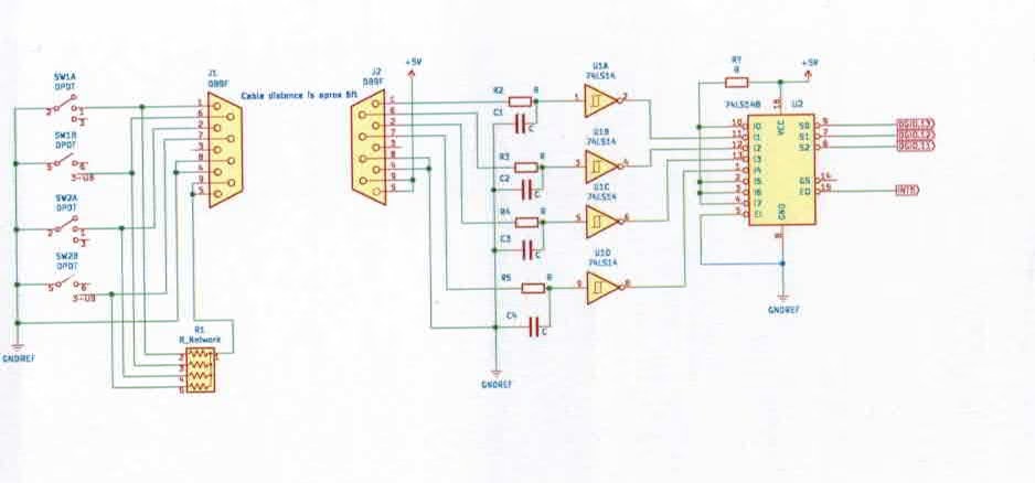
     mayermakes hi,  Mike I tend to disagree in my sim, the Arduino has normally 6 feet of cable between itself, and an avionics head. I don't want to troubleshoot a problem (like why is it a two or three when it should be one.) so be a big spender and waste about 50 cents. the part is a SN74x14N and it gives you 4 Shmitt Triggers in the package. This guarantees a square signal with no bounce NADA - ZIP, GONE, POOF.  I personally don't like good enough as it is bound to FAIL... LTRGTR by the way shabaz here is what I normally do: and this is from the Fuel Load Meter blogs:

    image

    BTW I later removed the SN74LS148 priority encoder you could have two positions on at the same time. 

    • Cancel
    • Vote Up +1 Vote Down
    • Sign in to reply
    • Cancel
  • scottiebabe
    scottiebabe over 2 years ago in reply to phoenixcomm

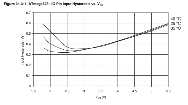
    Very fancy phoenixcomm! Many microcontrollers have Schmitt triggered inputs built-in  (at least the Microchip pic's do). I have never used an Arduino in my life but it looks like the atmega328 does too...

    image

    • Cancel
    • Vote Up 0 Vote Down
    • Sign in to reply
    • Cancel
  • phoenixcomm
    phoenixcomm over 2 years ago in reply to scottiebabe

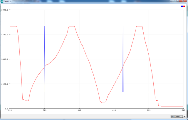
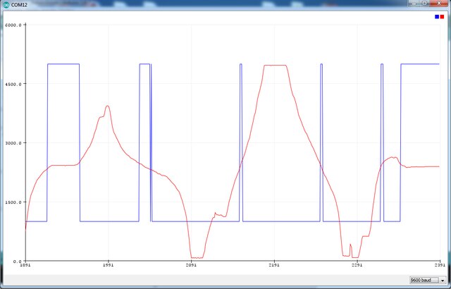
     scottiebabe I don't believe it does.  btw 2.5v is not a logic level I have two photos for you

    imageimage

    these came from https://forum.arduino.cc/t/rising-interrupts-behaves-as-chance-on-mega2560/570267/13 (new window)

    • Cancel
    • Vote Up +1 Vote Down
    • Sign in to reply
    • Cancel
  • scottiebabe
    scottiebabe over 2 years ago in reply to phoenixcomm

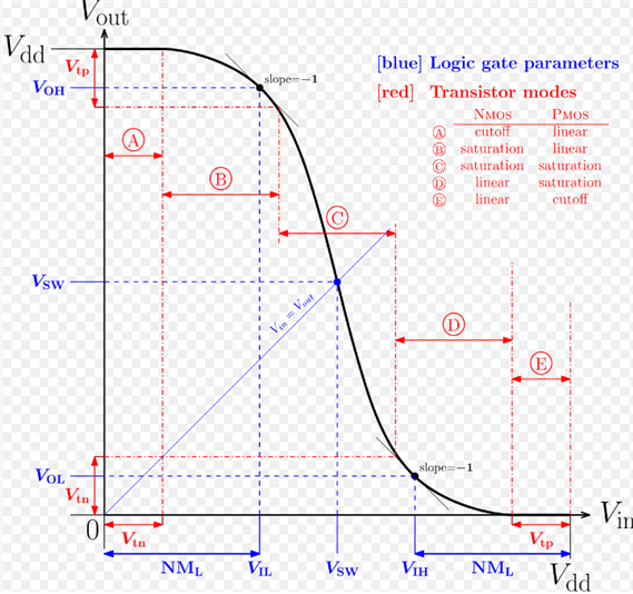
    Very interesting! *shrug* I don't know arduinos... The VTC curve of an inverter tends to have the input high/low threshold near Vdd/2 

    image 

    Yay another rabbit hole! The Rp2040 (pi pico) is supposed to have Schmitt triggered inputs I will try and measure the input thresholds.

    • Cancel
    • Vote Up +1 Vote Down
    • Sign in to reply
    • Cancel
  • phoenixcomm
    phoenixcomm over 2 years ago in reply to colporteur

    I'm so sorry, but I use I use a lot of Wire-Wrap®, on PCB as I have the tooling and lots of wire. I normally never get to the  PCB stage, unless the parts count gets ludicrous.  Below is a demo of Wire-Wrap®,

    You don't have permission to edit metadata of this video.
    Edit media
    x
    image
    Upload Preview
    image

    • Cancel
    • Vote Up +1 Vote Down
    • Sign in to reply
    • Cancel
  • phoenixcomm
    phoenixcomm over 2 years ago in reply to scottiebabe

    yes all true, but when you have a mechanical thing like a switch, you get lots of bounce on both ends rising and falling, much better to be safe than sorry. and we are talking about only 3 quarters (75 cents US) at most. look at a switch with your scope....  you will be shocked!!, go back a day and look at my first reply, go to that page (link), and in the photo I give credit for the work...

    • Cancel
    • Vote Up +1 Vote Down
    • Sign in to reply
    • Cancel
  • scottiebabe
    scottiebabe over 2 years ago in reply to phoenixcomm

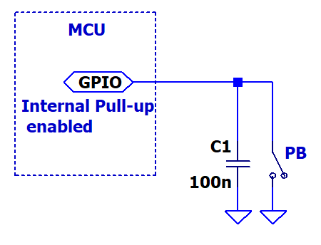
    In my own projects I sometimes even interrupt on the falling edge of a PB to GND Scream The parallel filter capacitor lengthens the rise time to a value where the switch contacts have stop chattering... 

    • Cancel
    • Vote Up +1 Vote Down
    • Sign in to reply
    • Cancel
  • phoenixcomm
    phoenixcomm over 2 years ago in reply to scottiebabe

     scottiebabe that is only a stop gap. spend a buck and get yourself some 74x14N  Schmitt triggers. LOL

    • Cancel
    • Vote Up +1 Vote Down
    • Sign in to reply
    • Cancel
  • scottiebabe
    scottiebabe over 2 years ago in reply to phoenixcomm

    LOL a whole dollar, but yes I have the 74 cmos version and the CD40106 inverting Schmitt triggers both way more useful than a 555 Scream

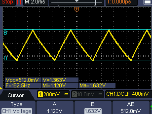
    Also confirmed on RP2040, I wired up the following with 10k and 1 uF

    image

    image

    Approximately 500 mV of hysteresis with VCCIO at 3.3V.

    • Cancel
    • Vote Up +2 Vote Down
    • Sign in to reply
    • Cancel
  • phoenixcomm
    phoenixcomm over 2 years ago in reply to scottiebabe

     scottiebabe  woh, there. I never said anything about a 555. BTW  works great for debounce on a matrix though.  I  said for switches use a 74x14N 2 resistors and a cap!!

    • Cancel
    • Vote Up +1 Vote Down
    • Sign in to reply
    • Cancel
  • scottiebabe
    scottiebabe over 2 years ago in reply to phoenixcomm

    lol Very nice. For a one off proto I don't always gild the lily and keep it simple...

    imageimage

    Without capacitor, CH1 SW, CH2 MCU output of the switch input inverted

    image

    With capacitor (10nf in this case)

    image

    In this case 10 nF is too small for the magnitude of pull-up current on the rp2040, it was just the first value I came across ... 

    • Cancel
    • Vote Up +1 Vote Down
    • Sign in to reply
    • Cancel
Reply
  • scottiebabe
    scottiebabe over 2 years ago in reply to phoenixcomm

    lol Very nice. For a one off proto I don't always gild the lily and keep it simple...

    imageimage

    Without capacitor, CH1 SW, CH2 MCU output of the switch input inverted

    image

    With capacitor (10nf in this case)

    image

    In this case 10 nF is too small for the magnitude of pull-up current on the rp2040, it was just the first value I came across ... 

    • Cancel
    • Vote Up +1 Vote Down
    • Sign in to reply
    • Cancel
Children
  • colporteur
    colporteur over 2 years ago in reply to scottiebabe

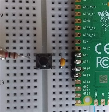
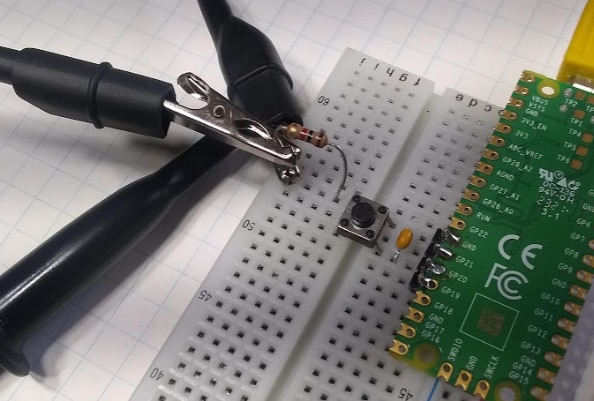
    You pic has a resistor, switch and cap but schematic only the switch and cap. Is the resistor the pullup?

    • Cancel
    • Vote Up +1 Vote Down
    • Sign in to reply
    • Cancel
  • scottiebabe
    scottiebabe over 2 years ago in reply to colporteur

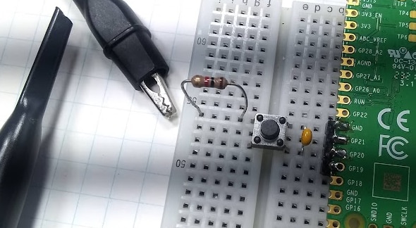
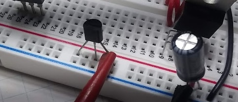
    You have a keen eye! Both ends of the resistor are connected to ground. I find using a shorted 2-terminal component makes for a more reliable connection to alligator clips and mini-grabbers, there is no other reason for the resistor other than using its leads as ground connection points.

    imageimage

    Sometimes I even use three terminal components as a connection point...

    image

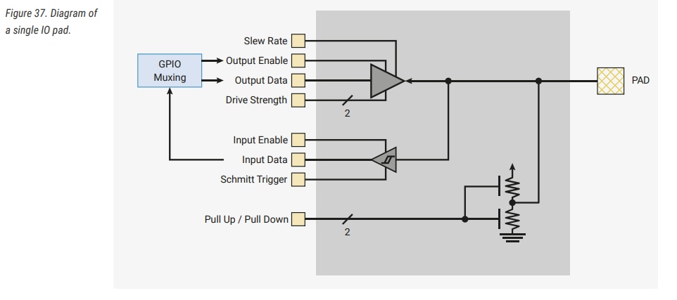
    The pull-up resistor I am using is embedded in the MCU. Most MCU included a software controllable pull-up (usually a pull-down too) resistor on each of the GPIO pins. In the case of the RP2040 a GPIO pin has the following design

    image

    So in my uPython code I can simply ask for the pull-up to be enabled:

    image

    But all of this requires your MCU has a Schmitt triggered input. As a slow rising edge on an ordinary logic input is highly susceptible to noise near its switching threshold. If you look at the slope of the VTC curve I showed above near the threshold point a small change in input voltage results in a large change in output voltage (ie the inverter has significant gain). So an ordinary logical input could falsely toggle a few times near the threshold point from RFI, power supply ripple, or just thermal noise.. But with Schmitt triggered inputs, very large excursions are needed for the input buffer to switch states, so it intrinsically ignores most of the common noise sources within reason. 

    • Cancel
    • Vote Up +1 Vote Down
    • Sign in to reply
    • Cancel
  • colporteur
    colporteur over 2 years ago in reply to scottiebabe

    My data collection through images is stronger than through text. I tend to use the images as the stucco wire to hold the text information. If the two are incongruent my mind tends to cycle reset.

    • Cancel
    • Vote Up 0 Vote Down
    • Sign in to reply
    • Cancel
  • scottiebabe
    scottiebabe over 2 years ago in reply to scottiebabe

    Technical forums are great, so many great tidbits of knowledge shared in this thread!

    One more demonstration showing why a schmitt trigger is an important part of the solution.

    I wrote a simple PIO program to read the debounced push-button input pin and output the value read on another GPIO pin.

    @rp2.asm_pio(out_shiftdir=PIO.SHIFT_RIGHT,out_init=[PIO.OUT_HIGH])
    def bufpio():
        wrap_target()
        in_(pins,1)
        mov(osr,isr)
        out(pins,1)
        wrap()

    With the schmitt trigger enabled we get one nice clean transition from low to high (and visavera)

    Yellow: PB Input pin

    Blue: GPIO Output pin

    image

    With the schmitt trigger disabled the RP2040 can't make up its mind whether the input is high or low when the input is near the GPIO pins logic input threshold voltage

    image image

    image

    • Cancel
    • Vote Up +4 Vote Down
    • Sign in to reply
    • Cancel
element14 Community

element14 is the first online community specifically for engineers. Connect with your peers and get expert answers to your questions.

  • Members
  • Learn
  • Technologies
  • Challenges & Projects
  • Products
  • Store
  • About Us
  • Feedback & Support
  • FAQs
  • Terms of Use
  • Privacy Policy
  • Legal and Copyright Notices
  • Sitemap
  • Cookies

An Avnet Company © 2025 Premier Farnell Limited. All Rights Reserved.

Premier Farnell Ltd, registered in England and Wales (no 00876412), registered office: Farnell House, Forge Lane, Leeds LS12 2NE.

ICP 备案号 10220084.

Follow element14

  • X
  • Facebook
  • linkedin
  • YouTube