element14 Community
element14 Community
    Register Log In
  • Site
  • Search
  • Log In Register
  • About Us
  • Community Hub
    Community Hub
    • What's New on element14
    • Feedback and Support
    • Benefits of Membership
    • Personal Blogs
    • Members Area
    • Achievement Levels
  • Learn
    Learn
    • Ask an Expert
    • eBooks
    • element14 presents
    • Learning Center
    • Tech Spotlight
    • STEM Academy
    • Webinars, Training and Events
    • Learning Groups
  • Technologies
    Technologies
    • 3D Printing
    • FPGA
    • Industrial Automation
    • Internet of Things
    • Power & Energy
    • Sensors
    • Technology Groups
  • Challenges & Projects
    Challenges & Projects
    • Design Challenges
    • element14 presents Projects
    • Project14
    • Arduino Projects
    • Raspberry Pi Projects
    • Project Groups
  • Products
    Products
    • Arduino
    • Avnet Boards Community
    • Dev Tools
    • Manufacturers
    • Multicomp Pro
    • Product Groups
    • Raspberry Pi
    • RoadTests & Reviews
  • Store
    Store
    • Visit Your Store
    • Choose another store...
      • Europe
      •  Austria (German)
      •  Belgium (Dutch, French)
      •  Bulgaria (Bulgarian)
      •  Czech Republic (Czech)
      •  Denmark (Danish)
      •  Estonia (Estonian)
      •  Finland (Finnish)
      •  France (French)
      •  Germany (German)
      •  Hungary (Hungarian)
      •  Ireland
      •  Israel
      •  Italy (Italian)
      •  Latvia (Latvian)
      •  
      •  Lithuania (Lithuanian)
      •  Netherlands (Dutch)
      •  Norway (Norwegian)
      •  Poland (Polish)
      •  Portugal (Portuguese)
      •  Romania (Romanian)
      •  Russia (Russian)
      •  Slovakia (Slovak)
      •  Slovenia (Slovenian)
      •  Spain (Spanish)
      •  Sweden (Swedish)
      •  Switzerland(German, French)
      •  Turkey (Turkish)
      •  United Kingdom
      • Asia Pacific
      •  Australia
      •  China
      •  Hong Kong
      •  India
      •  Korea (Korean)
      •  Malaysia
      •  New Zealand
      •  Philippines
      •  Singapore
      •  Taiwan
      •  Thailand (Thai)
      • Americas
      •  Brazil (Portuguese)
      •  Canada
      •  Mexico (Spanish)
      •  United States
      Can't find the country/region you're looking for? Visit our export site or find a local distributor.
  • Translate
  • Profile
  • Settings
Arduino
  • Products
  • More
Arduino
Arduino Forum X9C503 works with ESP32?
  • Blog
  • Forum
  • Documents
  • Quiz
  • Events
  • Polls
  • Files
  • Members
  • Mentions
  • Sub-Groups
  • Tags
  • More
  • Cancel
  • New
Join Arduino to participate - click to join for free!
Actions
  • Share
  • More
  • Cancel
Forum Thread Details
  • State Suggested Answer
  • Replies 17 replies
  • Answers 1 answer
  • Subscribers 385 subscribers
  • Views 2175 views
  • Users 0 members are here
Related

X9C503 works with ESP32?

Ricodora
Ricodora over 1 year ago

I can't get X9C503 to work with ESP32 but it can with Arduino Mega.

What do I need --> To be able to operate the X9C503 to lower the volume of an audio line input. I don't want to use common manual potentiometers.
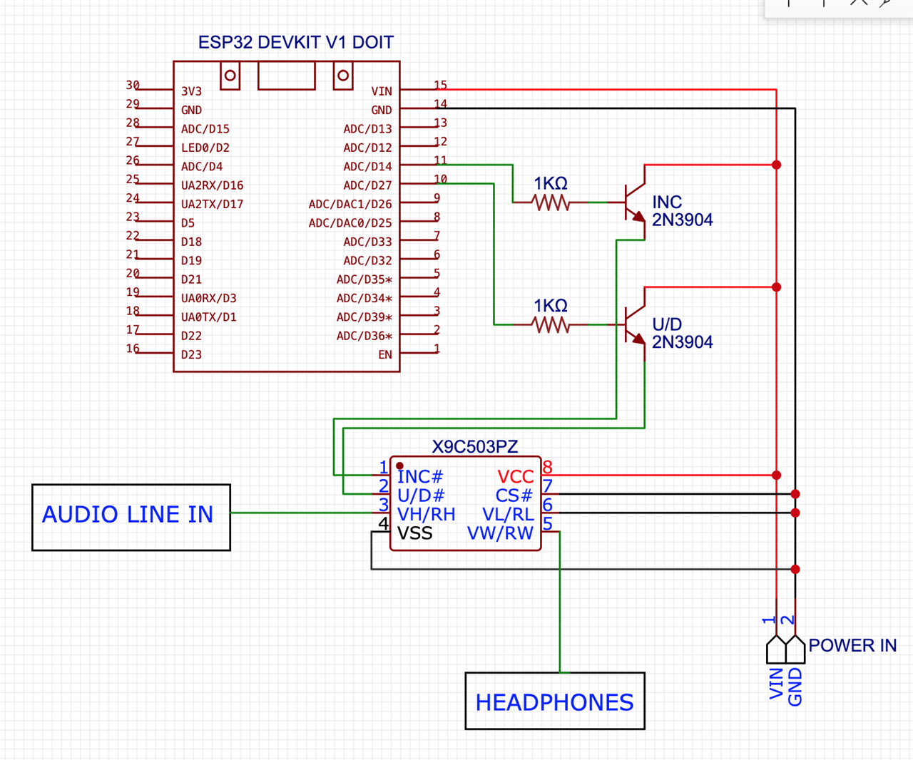
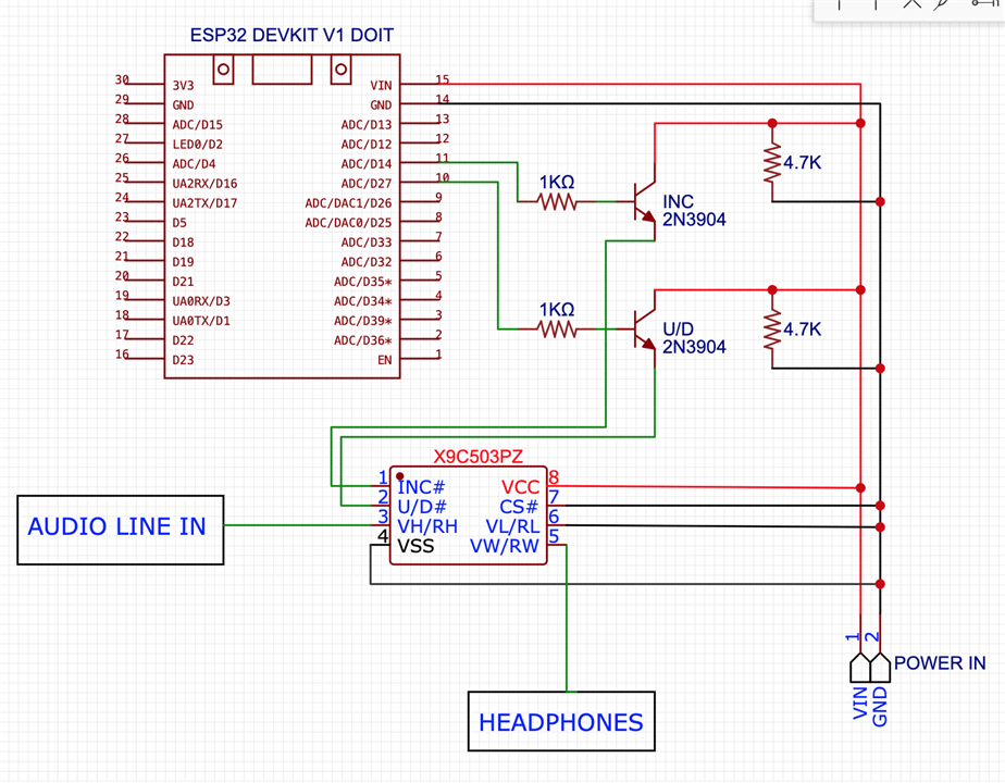
X9C503 Scheme:

INC__| o o | VCC
U/D__| o o | CS
RH___| o o | RL
GND__| o o | Rwiper

In my case:
INC------| o o | VCC (5v)
U/D------| o o | GND
Audio in | o o | GND
GND------| o o | Salida

On Arduino Mega I connect everything directly to the board and the operation is correct.

In ESP32 if I connect it to the board it doesn't work, so I have used the 2N3904 diode for the 'INC', 'U/D' pins (I have also tried with 'CS' but Arduino Mega does it well being grounded), and It works but it doesn't do it well, I describe the problem:

You have to enter values between 0 and 99, and in general it does it well, for low values the volume goes down and for high values the volume goes up. I detected the problem by always entering the same value.

In this case it was '91', if I enter it several times in a row I get different results, normally the volume remains constant but sometimes it goes up, other times it goes down and even total silence occurs

With Arduino Mega I enter the '91' 500 times and the
The volume never changes, it is constant and its operation is always correct.

What could be the problem?
What other component can I use?

As an alternative, I have tried the FM62429, with ESP32 it works correctly, but it has the amplification function that does not suit me. For the line input I already use 22kΩ resistors, then the potentiometer and finally the MSGEQ7, it doesn't make much sense to change a potentiometer to lower the voltage and replace it with a component that can amplify. I can limit the FM62429 by code, for example, to 60% and only use it to lower the volume, although I don't think it is a very elegant solution.

Audio Line In -> 22kΩ resistors -> X9C503 -> MSGEQ7
Audio Line In -> 22kΩ resistors -> FM62429 -> MSGEQ7

Any ideas or suggestions?

[code]#include "X9C10X.h"
#define CSPIN 33
#define INCPIN 14
#define UDPIN 27
X9C503 pot;

void setup() {
Serial.begin(9600);
pot.begin(INCPIN, UDPIN, CSPIN); // pulse, direction, select
Serial.println("Introduce un valor entre 1 y 99");
}
void loop() {
if(Serial.available() != 0){
int value = Serial.parseInt();
if (value != 0) {
pot.setPosition(value, true);
delay(30);
Serial.print("Valor introducido: ");
Serial.println(value);
}
}
delay(100);
}[/code]
  • Sign in to reply
  • Cancel

Top Replies

  • michaelkellett
    michaelkellett over 1 year ago in reply to Ricodora +1
    Try adding resistors from the emitters of each of the 2 transistors to ground. There is nothing in your circuit to pull them down to 0V when the bases are pulled low except leakage current. If the…
  • michaelkellett
    michaelkellett over 1 year ago in reply to michaelkellett +1
    There is actually no need for the transistors at all, I would connect the control pins to the processor via a 10k resistor. MK
  • Ricodora
    Ricodora over 1 year ago in reply to michaelkellett +1 suggested
    I said the 4k7 resistor didn't work when I first assembled it wrong. Now that you've pointed out my mistake......IT HAS WORKED!!! What a great relief! mk you got it right, now if I enter the same value…
Parents
  • Ricodora
    0 Ricodora over 1 year ago

    image

    image

    • Cancel
    • Vote Up 0 Vote Down
    • Sign in to reply
    • Verify Answer
    • Cancel
  • michaelkellett
    0 michaelkellett over 1 year ago in reply to Ricodora

    Try adding resistors from the emitters of each of the 2 transistors to ground.

    There is nothing in your circuit to pull them down to 0V when the bases are pulled low except leakage current.

    If the slew rate (speed at which the voltage on the pins changes) of the ESP and Arduino are different this might account for why one works an the other does not.

    4k7 would be a suitable value.

    MK

    • Cancel
    • Vote Up +1 Vote Down
    • Sign in to reply
    • Verify Answer
    • Cancel
  • michaelkellett
    0 michaelkellett over 1 year ago in reply to michaelkellett

    There is actually no need for the transistors at all, I would connect the control pins to the processor via a 10k resistor.

    MK

    • Cancel
    • Vote Up +1 Vote Down
    • Sign in to reply
    • Verify Answer
    • Cancel
  • Ricodora
    0 Ricodora over 1 year ago in reply to michaelkellett

    Hi MK, thanks for your time.

    I have done the test that you propose. I upload a new image to verify that what I have done is correct. I am a programmer and I have no knowledge of electronics, although I have already designed my first PCB and little by little I am learning.

    X9C503 with ESP32 without transistors does not work, does nothing. In Arduino Mega I don't use transistors.

    If the problem is the response speed... ... ... ... I don't know what tests to do. I'm going to read up on the subject to see if I can think of any "non-random" test.

    image

    • Cancel
    • Vote Up 0 Vote Down
    • Sign in to reply
    • Verify Answer
    • Cancel
  • michaelkellett
    0 michaelkellett over 1 year ago in reply to Ricodora

    You have connected the resistors to the collectors of the transistors and to ground - this will do nothing at all except slightly warm the resistors.

    They must be connected to the emitters of the transistors, so that there is a path for current to ground to pull the X9C503 control pins to 0V when they are meant to be at a low logic level.

    What test gear do you have available ?

    MK

    • Cancel
    • Vote Up 0 Vote Down
    • Sign in to reply
    • Verify Answer
    • Cancel
  • Ricodora
    0 Ricodora over 1 year ago in reply to Ricodora

    After doing the test the behavior is the same, if I enter the same value I do not always get the same output. Apparently nothing has changed

    • Cancel
    • Vote Up 0 Vote Down
    • Sign in to reply
    • Verify Answer
    • Cancel
Reply
  • Ricodora
    0 Ricodora over 1 year ago in reply to Ricodora

    After doing the test the behavior is the same, if I enter the same value I do not always get the same output. Apparently nothing has changed

    • Cancel
    • Vote Up 0 Vote Down
    • Sign in to reply
    • Verify Answer
    • Cancel
Children
  • michaelkellett
    0 michaelkellett over 1 year ago in reply to Ricodora

    I think the mistake you are making is not measuring what is happening. You can't do electronics work without measuring things..

    I think you are saying that your ciruit does not work with the 4k7 resistors in either place or not there at all ?

    SO we need to measure the voltages on the pins of the X chip.

    For that you need a meter (but you had better tell what kind of meter you have because it can affect the results.)

    Ideally you would use an oscilloscope but you may not have access to one.

    MK

    • Cancel
    • Vote Up 0 Vote Down
    • Sign in to reply
    • Verify Answer
    • Cancel
  • Ricodora
    0 Ricodora over 1 year ago in reply to michaelkellett

    I said the 4k7 resistor didn't work when I first assembled it wrong. Now that you've pointed out my mistake......IT HAS WORKED!!! What a great relief! ClapClapClapClapClapClap

    mk you got it right, now if I enter the same value I ALWAYS get the same output

    So... Whenever I use a transistor to drive an IC at 5V, should I use the 4k7 resistor to ground so that it can take the LOW value?

    Interestingly I am using the 74HC4051N also with transistors and it works correctly without "the path to ground". Even though in this particular case it is working, should I use "the ground path"?

    Seems like a basic concept for IC usage, I'm happy

    I have a multimeter and I take the measurements, which with the little knowledge I have, I consider interesting. I have not shared it due to lack of experience in forums, in solving this type of problem, it has not occurred to me. There were certainly measurements that I did not understand but that an experienced person can interpret perfectly. Next time I'll do it from the beginning

    Image of the setup that worked:

    ESP32 driving an X9C503

    CODE

    [code]
    #include "X9C10X.h"
    #define CSPIN 33
    #define INCPIN 14
    #define UDPIN 27
    X9C503 pot;
    void setup() {
    Serial.begin(9600);
    pot.begin(INCPIN, UDPIN, CSPIN); // pulse, direction, select
    Serial.println("Introduce un valor entre 1 y 99");
    }
    void loop() {
    if(Serial.available() != 0){
    int value = Serial.parseInt();
    if (value != 0) {
    pot.setPosition(value, true);
    delay(30);
    Serial.print("Value: ");
    Serial.println(value);
    }
    }
    delay(100);
    }
    [/code]
    • Cancel
    • Vote Up +1 Vote Down
    • Sign in to reply
    • Verify Answer
    • Reject Answer
    • Cancel
  • michaelkellett
    0 michaelkellett over 1 year ago in reply to Ricodora

    The 74HC4051 is an 8 channel multiplexer - not sure how you could use it in this application - did you mis type the part number ?

    You might have meant the 74HC4050 which is a hex level shifter but for high voltage in, low voltage out - so OK for 5V parts to drive 3V parts but not good for 3V parts to drive 5V parts.

    MK

    • Cancel
    • Vote Up 0 Vote Down
    • Sign in to reply
    • Verify Answer
    • Cancel
  • Ricodora
    0 Ricodora over 1 year ago in reply to michaelkellett

    I use the 74HC4051N as a switch to change between the audio line input and the microphone input. The project I'm doing has more parts. I also use it to set the decibels on the MAX9814 microphone

    The circuit pictured is to show my testing and to run the X9C503 in isolation (a simple case to learn and test)

    I do projects with microcontrollers and LEDs. This was the last step to be able to configure the microphone and input line without using physical components such as switches or potentiometers. I have already integrated the X9C503 into my project, it works correctly and I can now manage the configurations from my mobile (android in my case)

    Thanks for your time

    • Cancel
    • Vote Up 0 Vote Down
    • Sign in to reply
    • Verify Answer
    • Cancel
  • michaelkellett
    0 michaelkellett over 1 year ago in reply to Ricodora

    Sorry, I misunderstood your reference to the 4051.

    Happy to hear your system is working now.

    MK

    • Cancel
    • Vote Up 0 Vote Down
    • Sign in to reply
    • Verify Answer
    • Cancel
element14 Community

element14 is the first online community specifically for engineers. Connect with your peers and get expert answers to your questions.

  • Members
  • Learn
  • Technologies
  • Challenges & Projects
  • Products
  • Store
  • About Us
  • Feedback & Support
  • FAQs
  • Terms of Use
  • Privacy Policy
  • Legal and Copyright Notices
  • Sitemap
  • Cookies

An Avnet Company © 2025 Premier Farnell Limited. All Rights Reserved.

Premier Farnell Ltd, registered in England and Wales (no 00876412), registered office: Farnell House, Forge Lane, Leeds LS12 2NE.

ICP 备案号 10220084.

Follow element14

  • X
  • Facebook
  • linkedin
  • YouTube