Hello everyone,
I want to slide a Raspberry Pi Camera Module 3 along the X-axis, then the Z-axis, to center it on the target subject for a time-lapse.
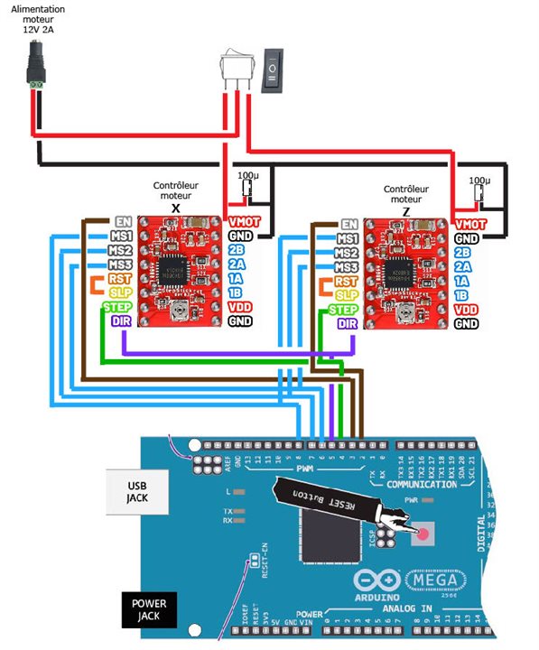
To do this, I have two CH-SM1545-M3xP0.5 micro motors (2-phase, 4-wire bipolar – 12V – with a threaded shaft travel of 80mm), and each will be controlled by its own A4988 motor controller. Selecting or powering on one of the two motors will be done with a KCD3 ON-OFF-ON SPDT 3-position toggle switch. Depending on the switch position (right or left), the target motor will be powered, while the other will be off. One of the powered motors will be controlled by a potentiometer.
Here is the electrical diagram for a single motor and its Arduino code. This works well with IR boundary sensors.

I have several questions about the electrical schematic.
I don't want to replicate my schematic for each motor. I'll end up with two 12V power supplies and two potentiometers for positioning the X-axis motor on the X-axis and the same for the Z-axis.
Can I power both A4988s with 12V via a third A4988?
Or should I place the toggle switch between the third A4988 and the other two, or is it possible to connect it directly to the Arduino Mega 2560?
Thank you for your time and ideas. I have little experience and am very curious.
/*
Arduino Mega + A4988
Capteurs (IR en U) + potentiomètre contrôle distance et direction après recul
--- Diagramme d’état : Moteur + Potar + Capteurs ---
[START / Moteur immobile]
|
| Potar bougé → au-delà zone morte
v
[Déplacement par potar]
|
| Capteur déclenché (IR)
v
[Recul 1 cm en micro-pas]
|
| Recul terminé
v
[Moteur en PAUSE après recul]
|
| Potar manipulé par l'utilisateur (delta > zone morte)
v
[Reprise contrôle par potar]
|
+--> [Déplacement par potar]
*/
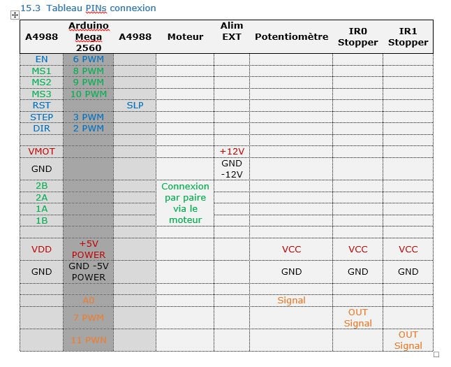
// Moteur PIN
const int MOTOR_DIR_PIN = 2;
const int MOTOR_STEP_PIN = 3;
const int MOTOR_ENABLE_PIN = 6;
// EndStop PIN signal
const int ENDSTOP_IR0 = 7;
const int ENDSTOP_IR1 = 11;
// EndStop MSx PIN
const int MS1_PIN = 8;
const int MS2_PIN = 9;
const int MS3_PIN = 10;
// Potentiomètre PIN Signal
const int POT_PIN = A0;
// Paramètres moteur
const int Nb_Recul = 200; // 1cm en full-step=400pas --- 0.5cm en full-step=200pas
const int microStepFactor = 16; // micro-pas pour recul
/*
Le moteur avance d’un pas à chaque impulsion STEP.
La vitesse du moteur dépend uniquement du temps entre deux impulsions.
motorDelayMax est grand, plus le mouvement minimal est lent et précis.
Plus motorDelayMin est petit, plus le moteur va vite.
*/
const int motorDelayMax = 1500; // microsecondes max STEP µs (lent) 1500 ≈ 1 mm/s
const int motorDelayMin = 400; // microsecondes min STEP µs (rapide) 400 ≈ 3,9 mm/s
/*
La zone morte (deadZone) est un intervalle central autour de la valeur neutre du potar où aucun mouvement du moteur n’est déclenché.
Exemple : const int deadZone = 50;
Si le potentiomètre est entre -50 et +50 autour du centre, le moteur reste immobile.
*/
const int deadZone = 200; // zone morte du potar
const int accelStep = 1; // incrément de lissage pour acceleration 2 4
bool reculEffectue = false; // vrai après recul
bool pauseAfterRecul = false; // moteur en pause après recul
int potRef = 0; // valeur de référence du potar après recul
int ir0LastState = 0;
int ir1LastState = 0;
int currentDelay = motorDelayMax;
bool potInverted = false; // true = inverser la direction du potar
// Fonction STEP simple
void stepMotor(int delayMicro) {
digitalWrite(MOTOR_STEP_PIN, HIGH);
delayMicroseconds(delayMicro);
digitalWrite(MOTOR_STEP_PIN, LOW);
delayMicroseconds(delayMicro);
}
void setup() {
pinMode(MOTOR_DIR_PIN, OUTPUT);
pinMode(MOTOR_STEP_PIN, OUTPUT);
pinMode(MOTOR_ENABLE_PIN, OUTPUT);
// pinMode(ENDSTOP_MECA, INPUT_PULLUP);
pinMode(ENDSTOP_IR0, INPUT);
pinMode(ENDSTOP_IR1, INPUT);
pinMode(MS1_PIN, OUTPUT);
pinMode(MS2_PIN, OUTPUT);
pinMode(MS3_PIN, OUTPUT);
// Micro-pas 1/16 pour recul
digitalWrite(MS1_PIN, HIGH);
digitalWrite(MS2_PIN, HIGH);
digitalWrite(MS3_PIN, HIGH);
digitalWrite(MOTOR_ENABLE_PIN, LOW);
delay(100); // stabilisation capteurs
ir0LastState = digitalRead(ENDSTOP_IR0);
ir1LastState = digitalRead(ENDSTOP_IR1);
}
void loop() {
// ===== Lecture potar =====
int potValue = analogRead(POT_PIN) - 512;
int potAbs = abs(potValue);
// Détermination direction potar avec inversion si activé
bool direction = potInverted ? (potValue < 0) : (potValue > 0);
// ===== Lecture capteurs =====
int ir0State = digitalRead(ENDSTOP_IR0);
int ir1State = digitalRead(ENDSTOP_IR1);
bool ir0Triggered = (ir0State == HIGH && ir0LastState == LOW);
bool ir1Triggered = (ir1State == HIGH && ir1LastState == LOW);
// ===== Recul 1 cm si capteur déclenché =====
if(!reculEffectue && (ir0Triggered || ir1Triggered)){
delay(50);
// Micro-pas pour recul
digitalWrite(MS1_PIN, HIGH);
digitalWrite(MS2_PIN, HIGH);
digitalWrite(MS3_PIN, HIGH);
digitalWrite(MOTOR_DIR_PIN, !direction); // reculer dans sens opposé au potar
for(int i=0; i<Nb_Recul*microStepFactor; i++){
stepMotor(motorDelayMin);
}
// Recul terminé → moteur en pause
reculEffectue = true;
pauseAfterRecul = true;
potRef = potValue; // mémoriser la valeur du potar après recul
// Mise à jour états capteurs
ir0LastState = digitalRead(ENDSTOP_IR0);
ir1LastState = digitalRead(ENDSTOP_IR1);
return; // ne rien faire d'autre
}
// ===== Vérification pause après recul =====
if(pauseAfterRecul){
int deltaPot = abs(potValue - potRef);
if(deltaPot > deadZone){
// l'utilisateur a bougé le potar → reprise
pauseAfterRecul = false;
} else {
return; // moteur reste en pause
}
}
// ===== STEP proportionnel au potar avec acceleration =====
if(potAbs >= deadZone){
// Micro-pas 1/16 pour recul
digitalWrite(MS1_PIN, HIGH);
digitalWrite(MS2_PIN, HIGH);
digitalWrite(MS3_PIN, HIGH);
/*
// Passer en full-step pour potar
digitalWrite(MS1_PIN, LOW);
digitalWrite(MS2_PIN, LOW);
digitalWrite(MS3_PIN, LOW);
*/
digitalWrite(MOTOR_DIR_PIN, direction);
// Calcul vitesse cible selon potar
int targetDelay = map(potAbs, deadZone, 512, motorDelayMax, motorDelayMin);
targetDelay = constrain(targetDelay, motorDelayMin, motorDelayMax);
// Lissage acceleration/déceleration
if(currentDelay < targetDelay)
currentDelay += accelStep;
else if(currentDelay > targetDelay)
currentDelay -= accelStep;
currentDelay = constrain(currentDelay, motorDelayMin, motorDelayMax);
stepMotor(currentDelay);
// Autoriser un nouveau recul si le potar est utilisé après recul
if(reculEffectue){
reculEffectue = false;
}
}
// Mise à jour derniers états des capteurs
ir0LastState = ir0State;
ir1LastState = ir1State;
}