Hi,
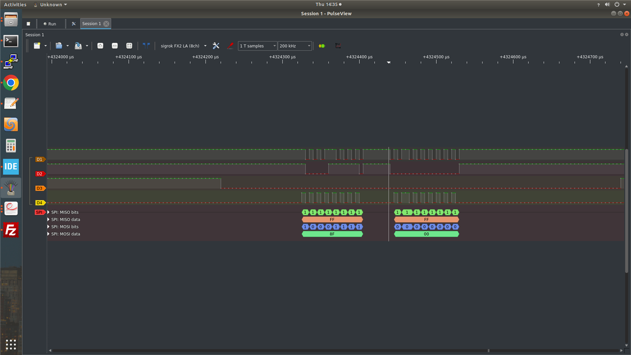
I am working on spi bus on maaxboard's j10 expansion pin. According to the MaaXBoard-Hardware_UserManual-V1.2-EN.pdf, 19-21-23-24th pins on it are ecspi1 outputs. When I write data over spi, I can get correct data from the mosi line but the miso and cs lines are completely inaccurate. Something might be wrong with the document or there might be another device on the line. So I edited the device tree file and the problem with the cs line was solved by when I changed the cs pinout. I am going to share some pictures which indicate data on ecspi1
if possible, could you please tell me where to download the schematics for Maaxboard?
Thanks in Advance!!
ecspi pinout configuration in dts:
&ecspi1{
	fsl,spi-num-chipselects = < 1 >;
	cs-gpios = <&gpio5 13 1 >, <&gpio3 2 1 >;
	pinctrl-names = "default";
	pinctrl-0 = <&pinctrl_ecspi1 >;
	status = "okay";
	#address-cells=<1>;
	#size-cells=<0>;
	spidev@0x00{
		#address-cellss=<1>;
		#size-cells=<0>;
		compatible = "spidev", "semtech,sx1301";
		spi-max-frequency = <1000000>;
		reg = <0>;
	};
	anotherspidev@0x00 {
		//status = "disabled";
		compatible = "spidev", "semtech,sx1301";
		spi-max-frequency = <400000>;
		reg = <1>;
	};
};
the first image is when I use gpio5 13(default) as the cs pin
the second image is when I use a different pin (gpio3 2) as the cs pin.
d1=> MISO
d2=> MOSI
d3=> CS
d4=> CLK


