element14 Community
element14 Community
    Register Log In
  • Site
  • Search
  • Log In Register
  • About Us
  • Community Hub
    Community Hub
    • What's New on element14
    • Feedback and Support
    • Benefits of Membership
    • Personal Blogs
    • Members Area
    • Achievement Levels
  • Learn
    Learn
    • Ask an Expert
    • eBooks
    • element14 presents
    • Learning Center
    • Tech Spotlight
    • STEM Academy
    • Webinars, Training and Events
    • Learning Groups
  • Technologies
    Technologies
    • 3D Printing
    • FPGA
    • Industrial Automation
    • Internet of Things
    • Power & Energy
    • Sensors
    • Technology Groups
  • Challenges & Projects
    Challenges & Projects
    • Design Challenges
    • element14 presents Projects
    • Project14
    • Arduino Projects
    • Raspberry Pi Projects
    • Project Groups
  • Products
    Products
    • Arduino
    • Avnet Boards Community
    • Dev Tools
    • Manufacturers
    • Multicomp Pro
    • Product Groups
    • Raspberry Pi
    • RoadTests & Reviews
  • Store
    Store
    • Visit Your Store
    • Choose another store...
      • Europe
      •  Austria (German)
      •  Belgium (Dutch, French)
      •  Bulgaria (Bulgarian)
      •  Czech Republic (Czech)
      •  Denmark (Danish)
      •  Estonia (Estonian)
      •  Finland (Finnish)
      •  France (French)
      •  Germany (German)
      •  Hungary (Hungarian)
      •  Ireland
      •  Israel
      •  Italy (Italian)
      •  Latvia (Latvian)
      •  
      •  Lithuania (Lithuanian)
      •  Netherlands (Dutch)
      •  Norway (Norwegian)
      •  Poland (Polish)
      •  Portugal (Portuguese)
      •  Romania (Romanian)
      •  Russia (Russian)
      •  Slovakia (Slovak)
      •  Slovenia (Slovenian)
      •  Spain (Spanish)
      •  Sweden (Swedish)
      •  Switzerland(German, French)
      •  Turkey (Turkish)
      •  United Kingdom
      • Asia Pacific
      •  Australia
      •  China
      •  Hong Kong
      •  India
      •  Korea (Korean)
      •  Malaysia
      •  New Zealand
      •  Philippines
      •  Singapore
      •  Taiwan
      •  Thailand (Thai)
      • Americas
      •  Brazil (Portuguese)
      •  Canada
      •  Mexico (Spanish)
      •  United States
      Can't find the country/region you're looking for? Visit our export site or find a local distributor.
  • Translate
  • Profile
  • Settings
Avnet Boards Forums
  • Products
  • Dev Tools
  • Avnet Boards Community
  • Avnet Boards Forums
  • More
  • Cancel
Avnet Boards Forums
MaaXBoard Hardware Design MaaXBoard-RT: PinMux, 2nd SPI, other features
  • Forum
  • Documents
  • Members
  • Mentions
  • Sub-Groups
  • Tags
  • More
  • Cancel
  • New
Join Avnet Boards Forums to participate - click to join for free!
Actions
  • Share
  • More
  • Cancel
Forum Thread Details
  • Replies 4 replies
  • Subscribers 322 subscribers
  • Views 849 views
  • Users 0 members are here
  • peripherals
  • pins
  • header
  • MaaXBoard-RT
  • Maaxboard RT
  • signals
  • alternatives
  • Pin Mux
Related

MaaXBoard-RT: PinMux, 2nd SPI, other features

tjaekel
tjaekel over 2 years ago

I was checking the headers J1 and J15, if I could have a 2nd SPI:
I want to implement "my" DualSPIder approach: one SPI master Tx, one SPI slave RX.
So, I have checked the header signals, pins and possible alternatives.

image

Figure 1: The AVNET J1 pin table (with corrections)

PinMux_Alternatives

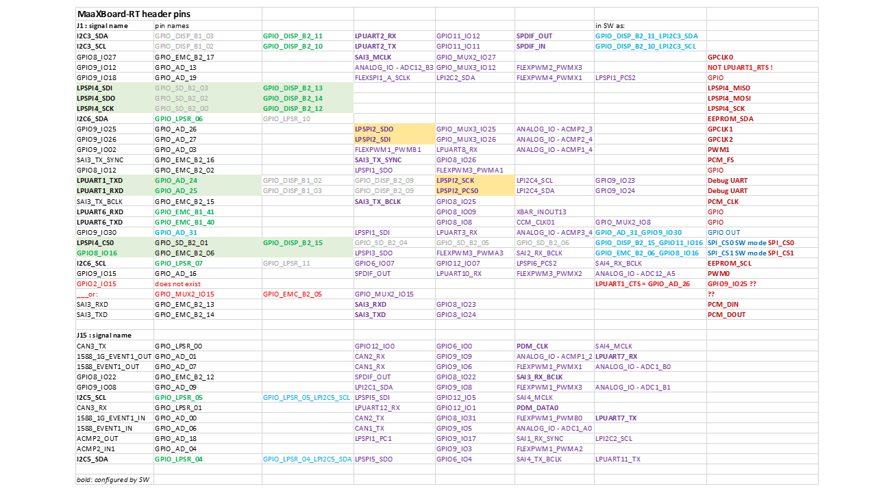
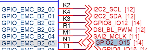
Figure 2: The pin names and possible (potential, not all) alternatives for the signals:
bold and green - what is configured on my project

QUESTION:
What is this GPIO2_IO15 as "GPIO/CTS"?
There is not a GPIO2 (just a GPIO_MUX2_IO15) and LPUART1_CTS is on a different pin.

What are the default features (signals)?

  • 2x I2C
  • 2x UART
  • 1s SPI
  • 1x SAI, bi-directional (but just as SAI Master)

plus on J15:

  • 1x CAN
  • 1x I2C

I have not listed here PWMs or ADC signals.

How to have a 2nd SPI?

A second SPI is possible, if you use the pins for LPUART1.
This is actually the Debug UART (the 3-pin header for the MCU-LINK).
But you can make it free and route the Debug UART, e.g. as LPUART6 (or even LPUART2 possible),
just change FW and connect MCU-LINK on other pins, to make LPUART1 free (as 2nd SPI).

So, a second SPI is available if you use another Debug UART.

What other features would be possible?

Based on the Alternatives for the pins - here what else could be configured and be available:

  • SAI3_MCLK : the master clock for PCM (if needed):
    BUT! the SAI3_RX_SYNC is not available. So, you can run the PCM as bi-directional) but just as Master.
    A PCM Slave is not possible!
  • SPDIF_OUT
  • SPDIF_IN
  • PDM with PDM_CLK and PDM_DATA0 (e.g. for an external PDM MIC) (on J15)
  • maybe two additional CAN (on J15)
  • or, maybe, another UART (on J15)
  • some more PWMs
  • Sign in to reply
  • Cancel
  • tjaekel
    tjaekel over 2 years ago

    BTW: I have checked J1 header pins against Raspberry Pi (RPi HAT) signals.
    Almost OK, except:

    The SPI_MOSI and SPI_MISO look also flipped!:
    The name in row as "Possible HAT Pin Function" is correct with RPi HAT, but MaaXBoard-RT has it flipped (SDI is MISO, SDO is MOSI).
    I would be suspicious if SPI works on RPi HAT with MaaxBoard-RT (or you can flip in SW the MISO and MOSI - not sure?).
    All other OK, at a first glance.

    Remark

    When you see on J1 header pin table stuff like "GPCLK0" or "PWM0" - it is the signal name on Raspberry Pi (RPi HAT), not MaaxBoard-RT signal.
    For instance: "PWM0" (as RPi HAT) is "FLEXPWM3_PWMX2" (on MaaxBoard-RT. So, if so, driven as PWM3).
    (the RPi HAT names are not the same as on MaaxBoard-RT real signals or not providing the "same" feature, like GPCLK0)

    So far, it looks OK (besides the SPI).
    And on RPi is not a "CTS" signal (for UART).

    So, still unclear what this pin J1, pin 36, is really on MaaxBoard-RT.

    • Cancel
    • Vote Up 0 Vote Down
    • Sign in to reply
    • Cancel
  • peterfenn
    peterfenn over 1 year ago in reply to tjaekel

    Pin 36 of the J1 header  is connected to GPIO_EMC_B2_05 on the RT1176 

    image

    • Cancel
    • Vote Up 0 Vote Down
    • Sign in to reply
    • Cancel
  • tjaekel
    tjaekel over 1 year ago in reply to peterfenn

    Hi peterfenn,

    where do you get this piece of schematics?
    May I get the full schematics as well?

    BTW:
    Yes, the pin is GPIO_EMC_B2_05 - but it is GPIO8_IO15 (8, not 2!) or GPIO2_MUX_IO15.

    It means: there is NOT a signal "GPIO2_IO15"
    (and it cannot, because GPIO2 and GPIO3 are tightly coupled GPIOs, as CM7_GPIO...,
    There are not GPIO2 and GPIO3: as regular it would be 8 or 9, but 2 is only CM7_GPIO_...).

    Could it be that the original schematics (you referring to), is a bit "wrong"?

    Best regards
    Torsten

    • Cancel
    • Vote Up 0 Vote Down
    • Sign in to reply
    • Cancel
  • tjaekel
    tjaekel over 1 year ago

    Here the final pinmux table I want to use...
    Bear in mind: I have verified the pin functions (before I would start my own PCB design...).
    e.g. pin J1, p36, is "GPIO8_IO15" or "GPIO_MUX2_IO15" --> as CM7_GPIO2...

    Maaxboard-RT-pinmux

    • Cancel
    • Vote Up 0 Vote Down
    • Sign in to reply
    • Cancel
element14 Community

element14 is the first online community specifically for engineers. Connect with your peers and get expert answers to your questions.

  • Members
  • Learn
  • Technologies
  • Challenges & Projects
  • Products
  • Store
  • About Us
  • Feedback & Support
  • FAQs
  • Terms of Use
  • Privacy Policy
  • Legal and Copyright Notices
  • Sitemap
  • Cookies

An Avnet Company © 2025 Premier Farnell Limited. All Rights Reserved.

Premier Farnell Ltd, registered in England and Wales (no 00876412), registered office: Farnell House, Forge Lane, Leeds LS12 2NE.

ICP 备案号 10220084.

Follow element14

  • X
  • Facebook
  • linkedin
  • YouTube