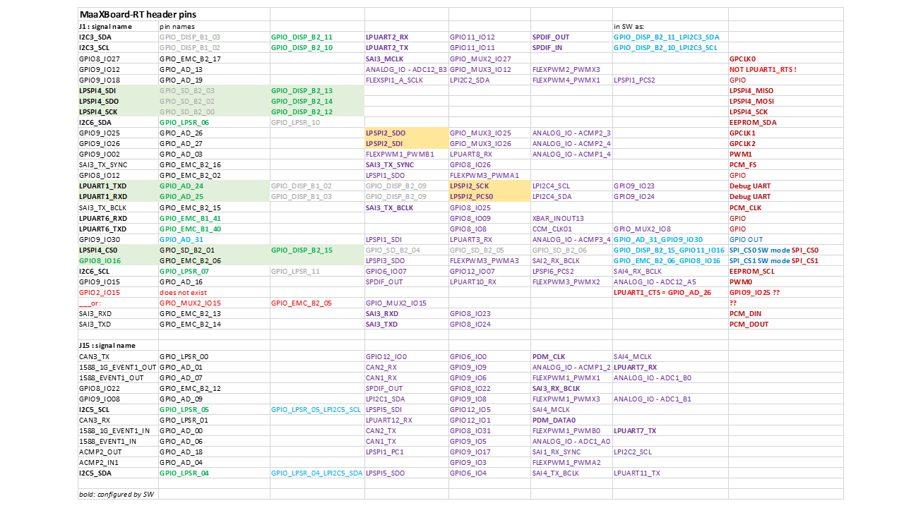
I was checking the headers J1 and J15, if I could have a 2nd SPI:
I want to implement "my" DualSPIder approach: one SPI master Tx, one SPI slave RX.
So, I have checked the header signals, pins and possible alternatives.

Figure 1: The AVNET J1 pin table (with corrections)

Figure 2: The pin names and possible (potential, not all) alternatives for the signals:
bold and green - what is configured on my project
QUESTION:
What is this GPIO2_IO15 as "GPIO/CTS"?
There is not a GPIO2 (just a GPIO_MUX2_IO15) and LPUART1_CTS is on a different pin.
What are the default features (signals)?
- 2x I2C
- 2x UART
- 1s SPI
- 1x SAI, bi-directional (but just as SAI Master)
plus on J15:
- 1x CAN
- 1x I2C
I have not listed here PWMs or ADC signals.
How to have a 2nd SPI?
A second SPI is possible, if you use the pins for LPUART1.
This is actually the Debug UART (the 3-pin header for the MCU-LINK).
But you can make it free and route the Debug UART, e.g. as LPUART6 (or even LPUART2 possible),
just change FW and connect MCU-LINK on other pins, to make LPUART1 free (as 2nd SPI).
So, a second SPI is available if you use another Debug UART.
What other features would be possible?
Based on the Alternatives for the pins - here what else could be configured and be available:
- SAI3_MCLK : the master clock for PCM (if needed):
BUT! the SAI3_RX_SYNC is not available. So, you can run the PCM as bi-directional) but just as Master.
A PCM Slave is not possible! - SPDIF_OUT
- SPDIF_IN
- PDM with PDM_CLK and PDM_DATA0 (e.g. for an external PDM MIC) (on J15)
- maybe two additional CAN (on J15)
- or, maybe, another UART (on J15)
- some more PWMs

